Water Heaters Repair Shop Manual Thermo Top Z Supplementary Heater Thermo Top E Thermo Top C Auxiliary Heater Type Thermo Top E - B Type Thermo Top Z/C - B Fuel Type Thermo Top E - D Type Thermo Top Z/C - D Diesel 04/2008 63378C_EN
List of Contents 1 Introduction 1.1 1.2 1.3 1.4 Scope and Purpose ............................................................................................................................... 101 Meaning of Warnings, Cautions, and Notes .......................................................................................... 101 Additional Documentation to be used .................................................................................................... 101 Safety Information and Regulations.
5 Troubleshooting 5.1 5.2 5.3 General Fault Symptoms ...................................................................................................................... 501 Error Messages during Functional Test with Diagnosis Tester Thermo Test ....................................... 502 Malfunctions.......................................................................................................................................... 503 5.3.1 Error Lockout by Malfunction of Heater ..................
9 Repair 9.1 General .................................................................................................................................................. 901 9.1.1 Work on Components after Disassembly .................................................................................... 901 9.2 Disassembly and Assembly................................................................................................................... 902 9.2.1 9.2.2 9.2.3 9.2.
List of Figures Thermo E and Top Z/C List of Figures 501 502 Fault Symptoms ......................................................................................................................................... 501 Error Messages.......................................................................................................................................... 502 701 702 703 704 Control Unit Connector Pin Assignment (Thermo Top E and C) .........................................................
Thermo Top E and Z/C 1 Introduction 1.1 Scope and Purpose This repair shop manual is intended to support familiarised personnel in the repair of the water heaters Thermo Top E, Thermo Top Z and Thermo Top C of the fuel and Diesel types. As their appearance is identical or similar, the heaters are marked by type on their identification plate with "Benzin" (fuel) or "Diesel".
1 Introduction must be observed. The use of the heater in "vehicles for the transportation of dangerous goods" (ADR) is not permitted. Thermo Top E and Z/C • the heater mode of operation – at least "on" or "off" – must be clearly visible. 1.4.2 General Safety Notes The examination is performed by presentation of the manufacturer’s operating/installation instructions.
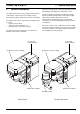
Thermo Top E and Z/C 2 2 General Description General Description The water heater Thermo Top Z (supplementary heater) is intended to compensate for the shortage in heat generated by engines optimised for low fuel consumption. The water heater Thermo Top E and C (auxiliary heater) is used to: • heat the vehicle cabin, • defrost the vehicle windscreens, • preheat water-cooled vehicle engines. The heater Thermo Top Z may be converted into an auxiliary heater using a retrofit kit.
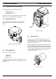
2 General Description 2.1 Thermo Top E and Z/C Combustion Air Fan Assembly The combustion air fan assembly includes the combustion air fan combustion air line inlet fuel supply inlet. The heater Thermo Top E and Z has the circulation pump mounted on the combustion air fan assembly. 2.1.1 Combustion Air Fan The combustion air fan delivers the air required for combustion from the combustion air inlet to the burner insert. Coolant outlet Coolant inlet Exhaust outlet Burner Housing 2.
Thermo Top E and Z/C 2.4 2 General Description Control Unit / Heat Exchanger The control unit / heat exchanger includes the control unit temperature sensor overheat protection heat exchanger connector terminal. 2.4.4 Heat Exchanger The heat exchanger transfers the heat generated by combustion to the coolant circuit. 2.5 CAUTION The control unit / heat exchanger and the burner housing represent an assembly and must not be disassembled.
2 General Description Page free for notes 4 Thermo Top E and Z/C
Thermo Top E and Z/C 3 Functional Description 3.1 Functional Description Thermo Top Z (Supplementary Heater) 3.1.1 Switch On / Starting Fuel When starting the vehicle engine the heater goes in standby. With a water circuit temperature below 60° C and an outside temperature below 5° C (option with outside temperature sensor) the starting sequence commences. The glow plug and the combustion air fan are activated.
3 Functional Description 3.2 Functional Description Thermo Top E and C (Auxiliary Heater) 3.2.1 Switch On Fuel When operating the "instant heat" switch button the timer display shows or when operating the switch on the Telestart transmitter the operating indicator light on the transmitter flashes. This puts the heater in standly. The glow plug, the combustion air fan and the circulation pump are activated.
Thermo Top E and Z/C 3 Functional Description 3.2.4 Auxiliary Heater in Supplementary Heater Function 3.2.4.1 Switch On When starting the engine the heater goes in standby (see 3.1.1). With the temperature of the water circuit below 60° C and the outside temperature below 5° C (option with external temperature sensor) the starting procedure is initiated. NOTE When operating in the supplementary heater function there will be no automatic trigger of the circulation pump and the vehicle's heating air fan. 3.
3 Functional Description Page free for notes 4 Thermo Top E and Z/C
Thermo Top E and Z/C 4 Technical Data 4.1 Thermo Top E 4 Technical Data Propellant for Thermo Top E (Fuel): The proper fuel is the fuel specified by the vehicle manufacturer. Where no threshold values are specified technical data in the table are understood to include standard tolerances for heater units of ± 10 % at an ambient temperature of + 20° C. All electrical components are selected for a nominal voltage of 12 Volts.
4 Technical Data 4.2 Thermo Top E and Z/C Thermo Top Z/C (Heating Flow 5.0 kW) Propellant for Thermo Top Z/C (Fuel): The proper fuel is the fuel specified by the vehicle manufacturer Where no threshold values are specified technical data in the table are understood to include standard tolerances for heater units of ± 10 % at an ambient temperature of + 20° C. All electrical components are selected for a nominal voltage of 12 Volts.
Thermo Top E and Z/C 4.3 4 Technical Data Thermo Top Z/C (Heating Flow 5.2 kW) Propellant for Thermo Top Z/C (Fuel): The proper fuel is the fuel specified by the vehicle manufacturer Where no threshold values are specified technical data in the table are understood to include standard tolerances for heater units of ± 10 % at an ambient temperature of + 20° C. All electrical components are selected for a nominal voltage of 12 Volts.
4 Technical Data Page free for notes 4 Thermo Top E and Z/C
Thermo Top E and Z/C 5 Troubleshooting 5.1 General Fault Symptoms 5 Troubleshooting The following table (Fig. 501) lists possible fault symptoms of general nature for heaters in installed condition. CAUTION Troubleshooting requires profound knowledge about components and their theory of operation and may only be performed by trained personnel. In case of doubt functional interrelations may be derived from Sections 2 and 3.
5 Troubleshooting 5.2 Thermo Top E and Z/C Error Messages during Functional Test with Diagnosis Tester Thermo Test NOTE The following table (Fig. 502) lists possible error messages during the functional test with the diagnosis tester and their probable cause.
Thermo Top E and Z/C Glow plug short circuit 5 Troubleshooting Thermo Top Z: • Switched line short circuit to plus of power supply • Overload or short circuit of glow plug Thermo Top E und C: • Ground short in power supply line to glow plug Glow plug open circuit Open line to glow plug / flame sensor • Short circuit to plus of power supply • Rise in coolant temperature within 9 min after start is < 3 K (Thermo Top C only) Water pump short circuit Thermo Top Z: • Switched line short circuit to plus of
5 Troubleshooting Thermo Top E and Z/C 5.3.3.2 Error Lockout Reset Thermo Top E and C with "Telestart" Eliminate cause of trouble. Switch off heater using the instant heat switch on the timer or the Telestart hand transmitter and switch on again. If heater fails to switch on, perform error lockout reset according to 5.3.3.4. An error lockout due to overheating does not have an indication. The fuse is not blown in case of overheating.
Thermo Top E and Z/C 6 Functional Checkouts 6.1 General This section describes the tests on the heater and its components in installed and removed condition as well as the test of the Timer and the Telestart T60/T70 to prove serviceability. WARNING The heater must not be operated in enclosed areas like garages or workshops not provided with exhaust ventilation facilities. 6.
6 Functional Checkouts Thermo Top E and Z/C 6.2.2 Timer Functional Test (Thermo Top E and C) 6.2.2.2 Switch On Signal Test 6.2.2.1 Voltage Check 1. Remove cover using a small screw driver. 1. Operate "ON" button and check voltage between "–" and "OUT". Voltage is approx. 7 V with the timer connected to the control unit or 12 V with the output not connected. 2. Operate "ON" button again and check voltage between "–" and "OUT". Voltage is 0 V. 2. Loosen screw. 3. Disconnect plug from clock. 4.
Thermo Top E and Z/C 6 Functional Checkouts 6.2.5 Functional Test with Diagnosis Tester Thermo Test • • 3. Connect red battery terminal clamp to battery plus and black battery terminal clamp to battery minus of vehicle. NOTE For operation of diagnosis tester refer to operating instructions. If error messages are displayed during functional testing, perform troubleshooting according to Section 5.
6 Functional Checkouts Thermo Top E and Z/C 6.2.6 CO2 Setting NOTE The CO2 setting is performed with the diagnosis tester Thermo Test. For operation of diagnosis tester refer to operating instructions. CAUTION For starting heater diagnostic line must be disconnected. Connection of diagnosis tester with heater on and operating at full load (approx. 5 min after switch on). Change of CO2 value in increments by pressing OK key.
Thermo Top E and Z/C 7 Circuit Diagrams 7.1 General 7 Circuit Diagrams The connector pin assignment of control unit Thermo Top E and Z/C is shown in Fig. 701. The circuit diagrams (Fig. 702 and 703) show the electrical circuit of the heater in combination with Timer and Telestart T60. The circuit diagram (Fig. 704) shows the electrical circuit of Thermo Top Z.
7 Circuit Diagrams Thermo Top E and Z/C ϑ ϑ 4 Item A1 A2 A3 A4 B2 E F1 F2 F3 H1 K3 M1 M2 M3 P S1 S2 S5 X1 X2 X3 X4 X5 X6 X8 X9 Y1 Nomenclature Heater Control unit Connector box Telestart receiver Temperature sensor Glow plug / flame sensor Fuse 15 A Fuse 1 A Fuse 25 A LED (in item P) Relay (in item A3) Motor Motor Motor Timer, digital Switch for vehicle air fan Switch for vehicle air fan Switch Connection, 6-pole Connection, 2-pole Connection, 2-pole Connection, 2-pole Connection, 2-pole Connection, 2
Thermo Top E and Z/C 7 Circuit Diagrams X9 (75) 15 30 61 rt ϑ 2 1 ge sw 3 A3 F1 rt F2 rt 2 X1 + 3 A2 1 sw rt OUT +15 rt X6 X5 X4 5 P - I max.
7 Circuit Diagrams Thermo Top E and Z/C 1 ϑ ϑ 2 ϑ Item A1 A2 B2 E F1 M1 X13 X14 X15 X16 X17 X18 X19 Y1 Nomenclature Heater Control unit Temperature sensor Glow plug / flame sensor Fuse 20 A Motor Connection 2-pole Connection 6-pole Connection 2-pole Connection 2-pole Connection 2-pole Connection 2-pole Connection 2-pole Dosing pump Remark Thermo Top Z Wire Gauges Flat fuse SAE J 1284 combustion air fan water repellant water repellant water repellant water repellant water repellant water repellant
Thermo Top E and Z/C 8 Servicing 8.1 General This section describes the servicing procedures allowed on the heater when installed. 8 Servicing • inspect fuel lines and fuel filter for leakage. • inspect coolant circuit and circulation pump (Thermo Top E and C only) for leakage. • inspect hoses for cracks. • replace fuel filter, if installed. WARNING There is a potential danger of skin burns as the heater and its components may be very hot. 8.6 8.2 8.6.
8 Servicing Thermo Top E and Z/C Prior to the heater's first operation or after renewal of the coolant the cooling system must be carefully bled. The heater and the lines must be installed to ensure static venting. The coolant hoses supplied by Webasto must be installed, other hoses must meet at least the DIN 73411 requirement. The hoses are to be routed upwards as far as possible and without kinks to ensure proper venting. Hose connections must be protected against slippage using hose clamps.
Thermo Top E and Z/C 8 Servicing 8.6.2 Connection to Vehicle Fuel System In vehicles with carburettor or fuel injection including a return line the heater fuel system integration must be according to Fig. 802. Carburettor engines without return line must have the heater integrated in the fuel system's fuel supply line between fuel tank and vehicle fuel pump. NOTE A fuel supply line can normally be identified by the installation of a fuel filter.
8 Servicing Thermo Top E and Z/C correct hose clamp Preferred wrong bubble bubble Dosing Pump DP2 – Fuel – Fig. 805 Pipe/Hose Connection 8.6.2.2 Dosing Pump The dosing pump is a combined delivery, dosing and shut-off system and is subject to certain installation criteria (Fig. 803 and 806). Concerning the installation location of the dosing pump it must be ensured that the maximum pressure at the tapping location is below the permissible value (see table of 8.6.2.).
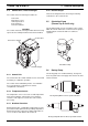
Thermo Top E and Z/C 8 Servicing combustion air must be taken in from and the exhaust vented to the exterior. The line feedthroughs must be sealed against splash water. 8.6.3 Air Intake Muffler The permitted installation position of the air intake muffler is between 0° and 90° pointing downwards. 0-90° 0-90° Fig. 807 Air Intake Muffler, Installation Position 8.6.3.1 General Remarks for Installation 8.6.
8 Servicing 8.7 Removal and Installation CAUTION In the heater installed condition only the circulation pump removal and installation is permitted should accessibility allow for such action (see 9.2.1). 8.7.1 Heater, Removal and Installation 8.7.1.1 Removal 1. Disconnect heater power supply by removing 20 A flat fuse (yellow) from Webasto fuse holder. Thermo Top E and Z/C 8.7.2 Timer, Removal and Installation Timer removal and installation is to be performed in accordance with Fig. 809.
Thermo Top E and Z/C 9 Repair 9.1 General 9 Repair This section describes the repairs that may be performed on the heaters Thermo Top Z and Thermo Top E and C when removed. Any further disassembly will void the warranty. After repairs a functional test must be performed. 9.1.1 Work on Components after Disassembly CAUTION All gaskets located between disassembled components must always be discarded and replaced. 9.1.1.1 Cleaning • All components disassembled must be cleaned.
9 Repair 9.2 Thermo Top E and Z/C Disassembly and Assembly 9.2.1.2 Installation 1. Slide spring band steel clamp (5, Fig. 901) onto hose end. 9.2.1 Circulation Pump, Replacement (Thermo Top E and C) 2. Position collar (1) on circulation pump (6) as required. 9.2.1.1 Removal 1. Remove cover (4, Fig. 901) and disconnect electrical connector of circulation pump. 3. Locate circulation pump (6) for installation and secure with clamp (2) and screw (7) on combustion air fan (3). 4.
Thermo Top E and Z/C 9 Repair 9.2.2 Combustion Air Fan, Replacement 4. Plug on electrical connections of combustion air fan. CAUTION In case of Thermo Top E and C the circulation pump must be removed first (see 9.2.1.1). 5. Install circulation pump as required (see 9.2.1.2). 9.2.2.1 Removal 7. Perform CO2 setting (see 6.2.6). 6. Plug on cover (6) and engage. 1. Carefully lever off cover (6, Fig. 902). 2. Disconnect electrical connector of combustion air fan. 3. Remove screws (11). 4.
9 Repair Thermo Top E and Z/C 3 2 2 3 2 1 8 10 1 9 11 1 6 1 Torque 4 Nm 2 Paper gasket 3 Rubber gasket 7 5 4 1 2 3 4 5 6 Combustion air fan Gasket Burner insert Gasket Burner housing Cover 7 8 9 10 11 Control unit / heat exchanger Glow plug / flame sensor Fuel pipe Screw (4) Screw (4) Fig.
Thermo Top E and Z/C 9 Repair 9.2.3 Burner Insert with Glow Plug / Flame Sensor, Replacement 9.2.4 Control Unit / Heat Exchanger with Burner Housing, Replacement CAUTION In case of Thermo Top E and C the circulation pump must be removed first (see 9.2.1.1). CAUTION In case of Thermo Top E and C the circulation pump must be removed first (see 9.2.1.1). 9.2.3.1 Removal 9.2.4.1 Removal 1. Remove combustion air fan (see 9.2.2.1). 1. Remove combustion air fan (see 9.2.2.1). 2.
9 Repair Page free for notes 6 Thermo Top E and Z/C
Thermo Top E and Z/C 10 10 Packaging, Storage and Shipping Packaging, Storage and Shipping 10.1 General The heater or its components shipped to Webasto Thermosysteme GmbH for testing or repair must be cleaned and packaged so that they are protected against damage during handling, shipping and storage. CAUTION When shipping a complete heater assembly it must be drained completely. No fuel is allowed to escape from a packaging or during shipping.
10 Packaging, Storage and Shipping Page free for notes 2 Thermo Top E and Z/C
http://dealers.webasto.com http://www.webasto.com Subject to modification © 2008 All Rights Reserved IDENT.-NR.