
Technical data


8 Servicing
Thermo Top Z/C
806
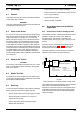
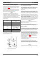
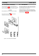
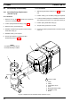
8.7.2 Timer, Removal and Installation
Timer removal and installation is to be performed in
accordance with Fig. 808. For initial installation use drilling
stencil. The electrical connection is shown in Section 7.
CAUTION
During installation do not exert pressure on display.
NOTE
Only the timer shown in Fig. 805 may be used in
combination with the heater.
Fig. 808 Timer, Removal and Installation
8.8 Initial Operation
After heater installation the coolant circuit as well as the
fuel supply system must be carefully bled observing the
relevant manufacturer's instructions.
During the heater test run inspect all coolant and fuel
connections for leakage and security. Should the heater
during operation enter an error lockout condition, perform
troubleshooting (see Section 5).