
Technical data

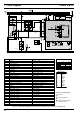

8 Servicing
Thermo Top Z/C
804
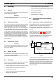
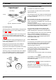
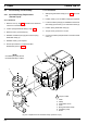
Fig. 805 Pipe/Hose Connection
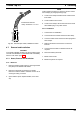
8.6.2.2 Dosing Pump
The dosing pump is a combined delivery, dosing and shut-
off system and is subject to certain installation criteria
(Fig. 803 and 806).
Concerning the installation location of the dosing pump it
must be ensured that the maximum pressure at the
tapping location is below the permissible value (see table
of 8.6.2.).
It is advantageous to mount the dosing pump in a cool
location. The ambient temperature must never exceed
+ 20 °C during operation.
Dosing pump and fuel lines must not be installed in
locations exposed to heat radiated by hot vehicle
components. A heat shield is to be provided as necessary.
The preferred installation location is near the tank.
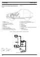
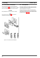
The dosing pump is to be attached with an anti-vibration
mount. The installation position is limited according to
Fig. 806 to ensure sufficient self-venting capability.
Fig. 806 Dosing Pump, Installation Position
8.6.2.3 Combustion Air Supply
A combustion air intake line is required.
The combustion air intake location must be protected
against splash water.
The combustion air line may routed in several bends (total
of 270°, smallest bending radius 50 mm). The maximum
line length is 1000 mm.
The combustion air must under no circumstances be
taken in from rooms accommodating persons. If the
heater is contained in an installation box, a vent hole of at
least 3 cm
2
is required.
Should the temperature within the installation box exceed
the permitted ambient temperature of the heater, the vent
hole must be enlarged after consulting Webasto.
The combustion air intake must be located so that
clogging by contamination is not to be expected. The
intake must
not
point in the direction of forward motion.
When installing the heater in the vicinity of the vehicle fuel
tank in a common installation compartment, the
combustion air must be taken in from and the exhaust
vented to the exterior. The line feedthroughs must be
sealed against splash water.
8.6.3 Exhaust Line
The exhaust line (inner diameter 22 mm) may be routed in
several bends (total of 270°, smallest bending radius
50 mm). The minimum line length is 500 mm, the
maximum length is 1000 mm.
The exhaust muffler is to be mounted near the heater,
however at least 200 mm away from the heater.
The exhaust muffler must not be installed near the
combustion air intake.
Heater operation without exhaust muffler is not permitted.
NOTE
Accumulations of condensate in the exhaust line must be
directly drained. A condensate drain hole (3 mm
Ø
) may
be provided as required.
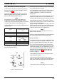
The exhaust line outlet must not point in the direction of
forward motion (Fig. 807)
Rigid pipes of unalloyed steel with a minimum wall
thickness of 1.0 mm or flexible hoses of alloyed steel only
may be used as exhaust ducts.
correct
wrong
hose clamp
bubble
bubble
Preferred