
Installation Manual

Webasto Air Top Installation Guide – AT2000STC
8
Air Top 2000STC Installation Guide 2018 | Webasto Thermo & Comfort Australia Pty Ltd.
3 Electrical System
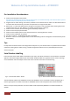
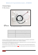
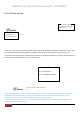
3.1 Main Harness
Do not cut or extend the controller wiring harness. This will void the warranty. If an extension is required for the
control element plug (Fig 12) (X9), an extension harness is available from Webasto.
We only recommend extending the battery positive (red) and negative (brown) wires. Correct wire size of 6mm to be
used to avoid any current or voltage drop in the circuit.
Ensure that the main plug is properly “home” in the ECU (Fig 12) (3). The main positive (red) and negative (brown)
has to be directly connected to the house battery and NOT via a master switch to ensure correct shut down cycle of
the heater.
Number
Function
1
Diagnostic Plug
2
Red Wire (Battery Positive)
3
Main Plug
4
Brown Wire (Battery Negative)
5
620 Ohm Resistor
6
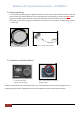
Rotary Controller (Potentiometer)
7
Multi-control digital
Fig 12 – AT2000STC Main Harness connections
1
2
3
4
5
6
7