
Installation Manual

Webasto Air Top Installation Guide – AT2000STC
6
Air Top 2000STC Installation Guide 2018 | Webasto Thermo & Comfort Australia Pty Ltd.
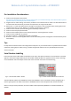
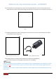
2.4 The combustion air inlet (Fig 3) (3) has a slot to accommodate the wires, ensure the fuel pump wires sit
neatly in this slot. Never run the wires through the combustion air inlet tube as it will create air restrictions.
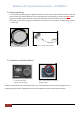
2.5 Attaching combustion air tube. A matching slot needs to be cut in one end of the combustion air tube to
accommodate the fuel pump wires.
2.6 Using the 25mm hose clamp, fix the combustion air tube to the inlet (Fig 3) (3).
Note: Ensure that the hose clamp & fuel pump wires are not rubbing.
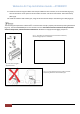
Under no circumstance may the combustion air be taken from areas occupied by people. The combustion air intake
opening must no t point in the direction of travel. It must be located so that it cannot become clogged with dirt or
road debris.
The combustion air must be extracted using a combustion air tube supplied in the kit and protected from dust and
water ingress.
Fig 8
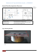
Fig 9 – Combustion Air Tube “V” cut.
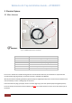
Fig 9a – Combustion Air Filter