Air Top Installation Guide - AT2000STC
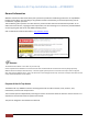
Webasto Air Top Installation Guide – AT2000STC General Information Webasto Thermo & Comfort Australia Pty Ltd is pleased to provide this installation guide for the Air Top 2000STC heating system. When used according to the guidelines stated in this booklet, you should expect many years of trouble-free, enjoyable operation. This installation guide represents our latest effort to produce the best technical documentation possible.
Webasto Air Top Installation Guide – AT2000STC Pre-Installation Considerations 1) Location and orientation of the heater. The heater may be fitted to the interior or exterior of the vehicle. If it is installed externally, ensure that the heater is fitted in a position where it is protected from water and dust ingress. 2) Length of hot air outlet ducting – the shorter, the better.
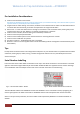
Webasto Air Top Installation Guide – AT2000STC Heater & Floor Mounting Bracket Dimensions 1 Heating Air Inlet 2 Heating Air Outlet 3 Combustion Air Inlet 4 Exhaust Gas Outlet 5 Fuel Inlet 6 Space Requirement for Heating Air Inlet 7 Space Requirement for Installation & Removal of Heater 8 Cable Outlet (Optional Right or Left) Fig 3 Floor Mounting Bracket 50mm Fig 4 4 Air Top 2000STC Installation Guide 2018 | Webasto Thermo & Comfort Australia Pty Ltd.
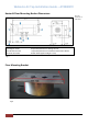
Webasto Air Top Installation Guide – AT2000STC Step by Step Installation 1. After checking what is under the floor to ensure clearance of tanks, chassis rails etc., Drill the 140mm floor mount bracket cut out. 2. Assembly of the heater 2.1 Assemble the heater to the bracket with the rubber gasket using the 10mm nuts and washers supplied in the kit.
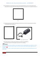
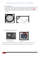
Webasto Air Top Installation Guide – AT2000STC 2.4 The combustion air inlet (Fig 3) (3) has a slot to accommodate the wires, ensure the fuel pump wires sit neatly in this slot. Never run the wires through the combustion air inlet tube as it will create air restrictions. Fig 8 2.5 Attaching combustion air tube. A matching slot needs to be cut in one end of the combustion air tube to accommodate the fuel pump wires. Fig 9 – Combustion Air Tube “V” cut. Fig 9a – Combustion Air Filter 2.
Webasto Air Top Installation Guide – AT2000STC 2.7 Attach the fuel line using the 10mm hose clamp & rubber fuel line connector, fix to the fuel inlet (Fig 3) (5), then fix the fuel line to the open end of the rubber connector and secure with another 10mm hose clamp. (Ref: Fig 8). 2.8 Install the stainless steel exhaust pipe, using the 25 mm exhaust clamp to the exhaust gas outlet (Fig 3) (5). The exhaust pipe temperature is above 250oC.
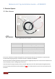
Webasto Air Top Installation Guide – AT2000STC 3 Electrical System 3.1 Main Harness 5 1 6 7 2 4 3 Fig 12 – AT2000STC Main Harness connections Number 1 2 3 4 5 6 7 Function Diagnostic Plug Red Wire (Battery Positive) Main Plug Brown Wire (Battery Negative) 620 Ohm Resistor Rotary Controller (Potentiometer) Multi-control digital Do not cut or extend the controller wiring harness. This will void the warranty.
Webasto Air Top Installation Guide – AT2000STC 3.1A 620 Ohm Resistor 620 Ω resistor supplied loose & in a separate pack within the kit. Connect 620 Ω resistor to wires marked ‘Temperature Sensor’ Please note – The black wire with blue stripes, with the mini spade terminals - labelled as ‘temperature sensor’, must be connected to the 620 Ω resistor which is supplied in the kit. Polarity does not matter. If the resistor is not connected when using the multi-controller the error code F94 will appear.
Webasto Air Top Installation Guide – AT2000STC 3.1 Fuel pump Wiring A 7m fuel pump harness (Fig 14) is supplied in the kit to connect to the fuel pump. Blue and brown, twin core harness connects to the two black wires out of the combustion air inlet (Fig 3) (3). Polarity does NOT matter. Plug kits are supplied; spade terminals or standard automotive electrical connections can be used. Note: Never run the wires through the combustion air inlet tube, as it will create air restrictions. Ref: Section 2 – (2.
Webasto Air Top Installation Guide – AT2000STC 4 Fuel Systems Fig 19 – Sample fuel system layout with Webasto 12Lt plastic fuel and vehicle fuel tank. For caravans, Webasto can supply a 12L plastic fuel tank with sight level gauge and a quick connect for the fuel line. With Motorhomes, fuel can be sourced out of the vehicle’s own fuel tank via a fuel pick up supplied with the kit. Note: When sourcing fuel from vehicle’s fuel tank, do not cut in to the return or supply line for two reasons: 1.
Webasto Air Top Installation Guide – AT2000STC 4.2 Installation of Fuel Stand Pipe When fuel is sourced out of the vehicle’s fuel tank, ensure that the stand pipe is installed on a flat surface and cut the stand pipe length so that it is 25mm from the bottom of the tank. See Fig 21/22. Fig 21 – Installing fuel extracting device – (Top Mount type) Fig 22 – 25mm - Fuel Extracting Device Install the tank extracting device as shown Fig 21 Shorten the immersion tube; the end should be approx.
Webasto Air Top Installation Guide – AT2000STC 4.4 Fuel Line Only Webasto supplied Fuel Line should be used for the fuel delivery to the heater. Use of any other fuel line will result in malfunction of the heater and will void warranty. To ensure correct connections, rubber hose connectors, 10 mm hose clamps and fuel line are supplied in the kit.
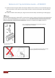
Webasto Air Top Installation Guide – AT2000STC 5 Ducting Layouts 5.1 Sample One Outlet layout Fig 26 Return Air 5.2 Sample Twin Outlet Layout Return Air Fig 27 COMPONENT 1 2 3 DESCRIPTION RETURN AIR Y-JUNCTION HOT AIR OUTLETS Fig 28 Ensure that the hot air and return air outlets are at least 1m away from each other or located in different directions to avoid any short cycle. Any short cycle in the system will affect the performance of the heater.
Webasto Air Top Installation Guide – AT2000STC 6 Enclosing the heater 1) Ensure that the area around the heater is not jam packed while using the compartment as storage as the heater itself and any ducting will get hot (70-80oC). 2) Heater can be boxed but it is recommended to have some breathing holes or grills on the enclosure to allow air flow in and around the heater. 3) The ducting has to be secured and ensure it cannot be crushed.
Webasto Air Top Installation Guide – AT2000STC 8 Basic Layout of Complete Installation COMPONENT DESCRIPTION 1 CONTROLLER 2 INTERFACE VEHICLE HARNESS 3 HEATER FUSES – F1 (15A) & F2 (10A) {Fig.
Webasto Air Top Installation Guide – AT2000STC 10 Multi-Control Set-Up & Operations Guide 10.1 Set-Up Heating Timer Ventilation 1 Menu Name 2 Menu Symbols 3 Time Setting Activated 4 Time 5 On / Off Button 6 Control Knob Settings Initial Start-Up When the Control unit is connected for the first time, a message about the Setting/Configuration of the heater is displayed.
Webasto Air Top Installation Guide – AT2000STC If your heater was not selected correctly at Initial Start-Up a Manual Reset is required. Press the On/Off Button to go to the Main Menu Screen and follow the following steps. Select the symbol “Settings” Press the Control Knob The “Quick Start” menu is displayed Turn the Control Knob clockwise 10 times until “Reset” is displayed Select “Reset” by pressing the Control Knob Press the Control Knob to confirm.
Webasto Air Top Installation Guide – AT2000STC 10.2 Timer Set-Up It is possible to program the Timer Setting 7 days in advance. The heater switches on automatically at the programmed time. Up to 3 time settings per day can be set, with a total of 21 time settings for the week.
Webasto Air Top Installation Guide – AT2000STC Turn the Control Knob to choose the desired heating mode Options available: Eco (Power Saving Mode); Normal (Comfort Heating); Boost (Rapid Heat) Press the Control Knob to confirm selection NOTE: Eco and Boost modes are not available for the AT2000STC Turn the Control Knob in order to choose the desired temperature (Temperature range: 5 - 35⁰C) Press the Control Knob to confirm selection The programmed timer is saved and shown on the display Press the Control
Webasto Air Top Installation Guide – AT2000STC 11 Preventive Maintenance To ensure trouble-free operation of your Webasto heater, please observe the following: 1) Operate heater for at least an hour once a month, regardless of the season 2) Keep return air inlet and hot air outlet free of obstructions to prevent overheating 3) Keep combustion air inlet and exhaust outlet tube free of dirt and obstructions 4) Change fuel filter annually (depending on the usage) 5) Bio Diesel or any fuel additive is not permi
Webasto Air Top Installation Guide – AT2000STC 12.1 Heater Flashing Fault Code Description 22 Air Top 2000STC Installation Guide 2018 | Webasto Thermo & Comfort Australia Pty Ltd.
Webasto Air Top Installation Guide – AT2000STC 23 Air Top 2000STC Installation Guide 2018 | Webasto Thermo & Comfort Australia Pty Ltd.
Webasto Air Top Installation Guide – AT2000STC 12.2 Heater Digital Multi Control display Fault Code Description 24 Air Top 2000STC Installation Guide 2018 | Webasto Thermo & Comfort Australia Pty Ltd.
Webasto Air Top Installation Guide – AT2000STC 25 Air Top 2000STC Installation Guide 2018 | Webasto Thermo & Comfort Australia Pty Ltd.
Webasto Air Top Installation Guide – AT2000STC 12.3 YouTube Tutorial Links YouTube tutorial on how to configure the multi controller to the correct model of heater, when there is T12 error. https://www.youtube.com/watch?v=qhXJOSPkqIM YouTube tutorial on the operation of the multi controller. https://www.youtube.com/watch?v=vvXBKKA8n6U YouTube tutorial to learn more about general troubleshooting AT2000STC https://www.youtube.com/watch?v=WfA-xpvCWHg YouTube tutorial when ‘No Power’ https://www.youtube.
Webasto Air Top Installation Guide – AT2000STC 12.
Webasto Air Top Installation Guide – AT2000STC Webasto Thermo & Comfort Australia Pty Ltd 423-427 The Boulevarde, Kirrawee NSW 2232 Australia svc-info@webasto.com www.webasto.com 28 Ph: +61 (0)2 8536 4800 Air Top 2000STC Installation Guide 2018 | Webasto Thermo & Comfort Australia Pty Ltd.