
Technical data


BBW 46 / DBW 46
9 Repair
909
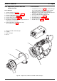
9.2.9 Replacement of Burner Head with
Combustion Pipe
9.2.9.1 Removal
1. Remove heater (see 8.7.1.1).
2. Break electrical connections (see 9.2.1.1).
3. Remove combustion air fan (see 9.2.7.1).
4. Remove glow plug (see 9.2.8.1).
5. Remove flame sensor (see 9.2.5.1).
6. Remove V-clamp (2, Fig. 906).
7. Engage two screw drivers in recess (4) and lever off
burner head (1) and remove.
8. Perform procedures on components after
disassembly (refer to 9.1.1).
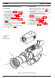
9.2.9.2 Installation
1. Locate burner head (1, Fig. 906) with combustion pipe
for assembly. Apply Copaslip (Ident. No. 105898)
between burner head and heat exchanger (3).
2. Slide burner head (1) with combustion pipe into heat
exchanger (3) and align as required.
3. Secure V-clamp and torque with 4.5 Nm.
4. Install flame sensor (see 9.2.5.2).
5. Install glow plug (see 9.2.8.2).
6. Install combustion air fan (see 9.2.7.2).
7. Install heater (see 8.7.1.2).
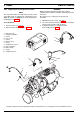
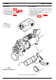
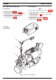
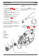
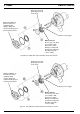
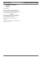
1 Burner head with combustion pipe
2 V-clamp
3 Heat exchanger
4 Recess
1
2
3
4
Fig. 906 Replacement of Burner Head with Combustion Pipe