
Technical data


BBW 46 / DBW 46
9 Repair
905
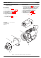
9.2.2.2 Installation
1. Apply Copaslip (Ident. No. 105898) to thread of
temperature limiter (2, Fig. 902) and manually screw
into heat exchanger (9).
2. Using a fork wrench tighten temperature limiter (2)
with a third of a turn. Maximum torque 1.5 Nm.
3. Fit protective cap (1).
4. Make electrical connections (see 9.2.1.2).
5. Install heater (see 8.7.1.2).
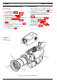
9.2.3 Replacement of Temperature Fuse
9.2.3.1 Removal
1. Remove heater (see 8.7.1.1).
2. Break electrical connections (see 9.2.1.1).
WARNING
When removing temperature fuse from installed condition
allow coolant to cool down sufficiently to prevent skin
burns.
Also depressurise cooling system and refit cap
afterwards.
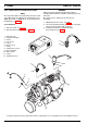
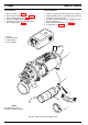
3. Unscrew temperature fuse (12, Fig. 902) from heat
exchanger (9) and remove together with O-ring (11).
4. Perform procedures on components after
disassembly (refer to 9.1.1).
9.2.3.2 Installation
1. Apply Copaslip (Ident. No. 105898) to thread of
temperature fuse (12, Fig. 902).
2. Manually screw temperature fuse (12) with O-ring (11)
into heat exchanger (9).
3. Ensure temperature fuse is screwed properly into heat
exchanger. Distance between surfaces to be approx.
0.8 mm.
4. Make electrical connections (see 9.2.1.2).
5. Install heater (see 8.7.1.2).
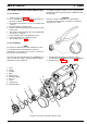
9.2.4 Replacement of Temperature Sensor
9.2.4.1 Removal
1. Remove heater (see 8.7.1.1).
2. Break electrical connections (see 9.2.1.1).
WARNING
When removing temperature sensor from installed
condition allow coolant to cool down sufficiently to prevent
skin burns.
Also depressurise cooling system and refit cap
afterwards.
3. Unscrew temperature sensor (8, Fig. 902) and
remove together with O-ring (7).
4. Perform procedures on components after
disassembly (refer to 9.1.1).
9.2.4.2 Installation
1. Apply Copaslip (Ident. No. 105898) to temperature
sensor (8, Fig. 902), manually screw with O-ring (7) in
place into heat exchanger (9) and tighten with 0.5 Nm.
2. Make electrical connections (see 9.2.1.2).
3. Install heater (see 8.7.1.2).
9.2.5 Replacement of Flame Sensor
9.2.5.1 Removal
1. Remove heater (see 8.7.1.1).
2. Break electrical connections (see 9.2.1.1).
3. Loosen lock screw (4, Fig. 902).
4. Withdraw flame sensor (6) on clamp together with O-
ring (5).
5. Perform procedures on components after
disassembly (refer to 9.1.1).
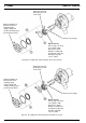
9.2.5.2 Installation
1. Apply non-acid grease to O-ring (5, Fig. 902) and
locate on flame sensor (vent port must remain open).
2. Slide flame sensor (6) into burner head (10).
3. Apply copper paste to lock screw (4) and screw into
burner head (10).
4. Make electrical connections (see 9.2.1.2).
5. Install heater (see 8.7.1.2).
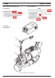
9.2.6 Replacement of Circulation Pump
NOTE
For a circulation pump mounted externally in vehicle the
following procedure is similar.
WARNING
When removing circulation pump from installed condition
allow coolant to cool down sufficiently to prevent skin
burns.
Also depressurise cooling system and refit cap
afterwards.