
Technical data
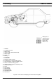


BBW 46 / DBW 46
8 Servicin
g
807
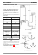
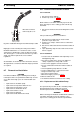
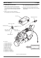
Fig. 807 Pipe/Hose Connection
8.6.3 Dosing Pump
The dosing pump is a combined delivery, dosing and shut-
off system and is subject to certain installation criteria
(Fig. 803 and 808).
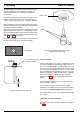
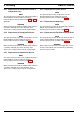
Fig. 808 Installation Position and Attachment of
Dosing Pump
8.6.3.1 Installation Location
Prior to installation of dosing pump ensure that the
pressure at the tapping location is less than 1.5 bar.
It is advantageous to mount the dosing pump in a cool
location as close as possible to the tank. The ambient
temperature must never exceed + 20 °C during operation.
Dosing pump and fuel lines must not be installed in
locations exposed to heat radiated by hot vehicle
components. A heat shield is to be provided as necessary.
The preferred installation location is near the tank.
8.6.3.2 Installation and Attachment
The dosing pump is to be attached with anti-vibration
mounts. The installation location is limited according to
Fig. 808 to ensure sufficient self-venting capability.
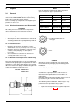
8.6.4 Fuel Filter
If there is the probability of contaminated fuel only the
Webasto filter, order no. 487 171, may be used.
Installation possibly vertical up to horizontal the most
(observe direction of flow).
8.6.5 Combustion Air Supply
Combustion air must under no circumstances be
extracted from rooms with persons. The combustion air
inlet must not point towards the forward direction of
motion. It must be located so that no clogging by
contamination, snow and splash water is to be expected.
The combustion air outlet must not be located above the
exhaust outlet.
If the heater is installed in the vicinity of the fuel tank in a
common installation compartment, combustion air must
be taken in from and the exhaust routed to the exterior.
The feedthroughs must be splash water proof.
If the heater is located in a closed installation box, a vent
hole of at least 6 cm
2
is required. If the temperature within
the installation box exceeds the maximum ambient
temperature allowed for the heater (see Technical Data),
the vent hole diameter must be increased after consulting
Webasto.
8.6.6 Exhaust Line
The exhaust line (inner diameter 22 mm) may have an
installation length of up to 5 m and several bends
(altogether 720°, smallest bending radius 50 mm). An
exhaust muffler may be fitted.
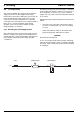
In order to ensure an angle of 90° ± 10° an attachment is
required not further than 150 mm away measured from
the exhaust pipe end (see Fig. 809).
The exhaust pipe outlet must not point in forward direction
of motion (see Fig. 809).
The exhaust pipe outlet must be located so that no
clogging by snow or mud is to be expected.
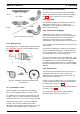
c
orrect
w
rong
hose clamp
bubble
bubble