
Installation Instructions
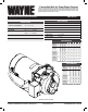

9
www.waynepumps.com
CWS Series
ELECTRICAL
Risk of electrical shock. This pump is designed
for indoor installation only, unless housed and protected from the
elements.
Installer un écran autour du tuyau d’entrée pour
éviter de piéger des nageurs, des animaux et des débris.
• This installation must be in accordance with the National Electric
Code and all applicable local codes and ordinances.
Do not connect to electric power supply until
unit is permanently grounded. Connect ground wire to approved ground
then connect terminal provided.
Ne pas connecter à l’alimentation électrique
tant que l’unité n’est pas mise à la terre en permanence. Brancher le fil
de mise à la terre à la masse approuvée puis raccorder la borne fournie.
A metal underground water pipe or well casing at least 10 feet long
makes the best ground electrode. If plastic pipe or insulated fittings
are used, run a wire directly to the metal well casing or use a ground
electrode furnished by the power company.
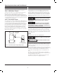
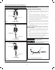
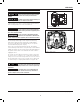
There is only one proper ground terminal on the unit. The terminal is
located under the pressure switch cover, is painted green and is identified
as GRD. The ground connection must be made at this terminal (Figure 9).
The ground conductor must not be smaller than the circuit conductors
supplying the motor.
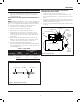
The voltage of power supply must match the voltage of the pump.
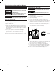
The motors can be converted to 115 or 230 volts by changing the
voltage selector to the desired voltage. Remove rear cover of motor
by unscrewing both screws to expose voltage selector. Rotate dial
so desired voltage is completely visible within notch (Figure 10).
Disconnect power and release all pressure from
the system before attempting to install, service, relocate or perform any
maintenance.
Débrancher de la source d’alimentation puis
dissiper toute la pression du système avant d’essayer d’installer, de
réparer, de déplacer ou de procéder à l’entretien.
L2
3
L1
1
Figure 9 - Electrical Connections
GROUND SCREW LINE
Figure 10 - Voltage Selector