Wayne-Dalton Corp. P.O. Box 67 Mt. Hope, OH 44660 (888) 827-3667 www.wayne-dalton.com Installation Instructions and Owner’s Manual Models: 3651-372 Covered under one or more of the following U.S. patents: 5,929,580/5,931,212/5,419,010/6,605,910/6,401,792/6,326,751/6,326,754/6,325,134/ 6,263,947/6,164,014/6,078,249/D466,141/D413,867/D413,579/D421,031/D472,568/ D472,910 other U.S.
Table of Contents Important Safety Instructions ○ ○ ○ ○ ○ ○ ○ ○ ○ ○ ○ ○ ○ ○ ○ ○ ○ ○ ○ ○ ○ ○ ○ ○ ○ ○ ○ ○ ○ ○ ○ ○ 3. Package Contents ○ ○ ○ ○ ○ ○ ○ ○ ○ ○ ○ ○ ○ ○ ○ ○ ○ ○ ○ ○ ○ ○ ○ ○ ○ ○ ○ ○ ○ ○ ○ ○ ○ ○ ○ ○ ○ ○ ○ ○ 4. Tools Needed ○ ○ ○ ○ ○ ○ ○ ○ ○ ○ ○ ○ ○ ○ ○ ○ ○ ○ ○ ○ ○ ○ ○ ○ ○ ○ ○ ○ ○ ○ ○ ○ ○ ○ ○ ○ ○ ○ ○ ○ ○ ○ ○ 5. Available Accessories ○ ○ ○ ○ ○ ○ ○ ○ ○ ○ ○ ○ ○ ○ ○ ○ ○ ○ ○ ○ ○ ○ ○ ○ ○ ○ ○ ○ ○ ○ ○ ○ ○ ○ ○ ○ ○ 5. Pre-Installation Inspection ○ ○ ○ ○ ○ ○ ○ ○ ○ ○ ○ ○ ○ ○ ○ ○ ○ ○ ○ ○ ○ ○ ○ ○ ○ ○ ○ ○ ○ ○ ○ ○ ○ 6.
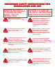
IMPORTANT SAFETY INSTRUCTIONS FOR INSTALLATION AND USE WARNING: INCORRECT INSTALLATION CAN LEAD TO SEVERE OR FATAL INJURY. FOLLOW INSTRUCTIONS. WARNING: IT IS VITAL FOR THE SAFETY OF PERSONS TO FOLLOW ALL INSTRUCTIONS. SAVE THESE INSTRUCTIONS. READ AND FOLLOW ALL INSTALLATION INSTRUCTIONS. Install only on a properly installed garage door. An improperly balanced door could cause severe injury.
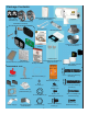
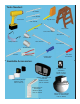
Package Contents: Three-button Transmitter (2) Gear Assemblies (2) 5 Button Wireless Keyless Entry (KEP3) W/ Hardware Opener Wall Station Assembly 6’ Power Cord Mounting Bracket Installation Video Light Fixture Assembly w/ Screw & Diffuser Owners Manual Wall Station Grease Packet (1) Reference Label Cable Keeper Assemblies W/ Hardware (2) (Right and Left) Entrapment Label Photoelectric Safety Sensors W/Hardware Hardware Kit: Disconnect Handle (1) 5/16 x 1-5/8” Hex Head Lag Screws (2) Disconnec
Tools Needed: 1/8” Drill Bit 3/16” Drill Bit Power Drill Tape Measure 3/32” Drill Bit Pencil Step Ladder 7/16” Socket Driver 3/8” Wrench 7/16” Socket 9/16” Wrench Safety Glasses 7/16” Wrench 9/16” Socket Ratchet Pliers/Wire Cutter Phillips Head Screwdriver Flat Head Screwdriver Available Accessories: 3-Button Mini RF Transmitter Model no: 3973 Part no: 302083 Infrared Safety Sensor Model no: 3967 Part no: 252118 5-Button Wall-Station RF Transmitter Model no: 3975 Part no: 302090 Keyless Entry R
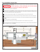
Pre-Installation Inspection Before installing Torsion idrive™, ensure your door system meets the following requirements. Follow the illustration below as a visual guide. CAUTION DO NOT INSTALL THIS OPENER ON YOUR DOOR UNLESS THE FOLLOWING ITEMS ARE MET. The torsion tube must be 1” in diameter. There must be at least 30-3/8" of clear torsion tube between the right (inside garage looking out) cable drum and the counterbalance spring.
Torsion idrive™ Installation MOUNTING LOCATION (2” X 6” RECOMMENDED) Step 1 If there are no suitable mounting surfaces to mount the opener, a strong mounting support will be needed. Securely fasten a wood (2" x 6" recommended) mounting surface for the opener. Make sure it is flush with the header and located to allow the opener to secure to it. Install the adjustable wall bracket to the studs in the wall plate. Loosely secure with the 5/1618 nuts and lock washers provided.
Step 3 1” TORSION GREASE PACKET TUBE GEAR ASSEMBLIES Lubricate both right hand and left hand gear assemblies, with the grease provided. Place the opener over the 1" GREASE torsion tube and ALL TEETH IN GEAR between the two gear assemblies. Center the opener mounting bracket over the mounting support. Lift the opener slightly and slide the left hand gear assembly over so that the left hand drive gear meshes with and rests on the teeth of the left hand gear assembly. Repeat for right hand gear assembly.
MOTOR DISCONNECT BEARING (ENGAGED) CENTER SPRING BRACKET ASSEMBLY DISCONNECT CABLE OPENER WARNING WHEN LEVELING THE OPENER TO THE TORSION TUBE DO NOT MAKE ANY ADJUSTMENTS TO THE CENTER SPRING BRACKET ASSEMBLY. REMOVING ANY LAG SCREWS HOLDING THE SPRING BRACKET TO THE WALL MAY RESULT IN SEVERE OR FATAL INJURY. LEVEL THE OPENER BY SIMPLY MOVING THE UNIT UP OR DOWN VERTICALLY. Pull on the disconnect cable that is located at the lower right hand side of the opener.
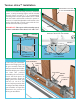
DISCONNECT CABLE MUST BE BETWEEN JAMBS/HEADER AND COUNTERBALANCE CABLE CABLE GUIDE BRACKET FLAGANGLE DISCONNECT CABLE HEADER COUNTER BALANCE CABLE FLAGANGLE Once the cable guide bracket is aligned, secure the bracket to the jamb, using (2) 1/4 x 1-1/2" lag screws. NOTE: It is recommended that 1/4" lag screw locations are pilot drilled using 1/8" drill bit. Disconnect cable must be routed behind counterbalance cable and it must not rub on the counterbalance cable.
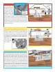
Step 8: Photoelectric Safety Sensor Installation Select a mounting position no more than 5 inches above the floor to center line of wall mounting bracket. The sending and receiving units should be mounted inside the door opening to minimize any interference by the sun. However, the sensors should be mounted as close to the door track or inside edge of the door as possible to offer maximum entrapment protection. It is very important that both wall brackets be mounted at the same height for proper alignment.
Photoelectric Safety Sensor Installation Continued WIRE ROUTING To locate the terminal block for the infrared sensor sender/receiver wires, you must first move the right hand gear assembly. Loosen the 3/8” square head bolt (refer to Step 4.) and slide the gear assembly away from the opener. Uncoil wires from photoelectric sensors and route wires up garage wall and along door header towards the right side of the opener power head.
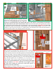
Pre-Operation Installation (2) PHILLIPS HEAD SCREWS Step 9: Wall Station Installation Locate a convenient place to mount wall station. To keep wall station out of the reach of children, measure at least five feet up from the floor and secure wall station base into wood wall framing using (2) phillips head screws. Use 2 of 3 holes that best align with wood framing. If fastening into drywall or concrete, proper anchors (not provided) will need to be used.
Step 10 WARNING PRIOR TO INSTALLING CABLE SPACER KEEPERS, CHECK FOR BROKEN OR FRAYED COUNTERBALANCE CABLES. OPERATING A DOOR WITH BROKEN OR FRAYED CABLE(S), MAY RESULT IN A SEVERE OR FATAL INJURY. CONTACT A QUALIFIED DOOR SERVICE PERSON TO REPLACE BROKEN OR FRAYED COUNTERBALANCE CABLES. WARNING DO NOT ATTEMPT TO REMOVE OR LOOSEN BOTTOM BRACKETS IN ANYWAY. THEY ARE UNDER EXTREME SPRING TENSION AND CAN CAUSE SEVERE OR FATAL INJURY. ROLLER BOTTOM BRACKET NOTE: The cable keeper must have a Min.
Step 11: Multi-Opener/Light Fixture Programming Switch Settings: Light Fixture If installing more than one opener in the same garage, the light fixtures can be programmed to only function with a desired opener. Leaving the light fixture as is from the factory may cause all light fixtures to light when any one of the openers are activated. The opener jumpers and light fixture switches need to be matched to allow for the opener to activate a specific light fixture.
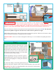
Step 12: Light Fixture Installation IMPORTANT! The light is turned on and off by an infrared (IR) signal sent from the opener to the light. Therefore, the light must be mounted in a location where it can always “see” the front face of the opener. Locate a duplex receptacle within line of sight of opener, when the door is in the open position. WARNING TO AVOID THE RISK OF ELECTRICAL SHOCK, THIS EQUIPMENT HAS A GROUNDING TYPE PLUG, THAT HAS A THIRD (GROUNDING) PIN.
WALL MOUNTING Depending on location, the light fixture may need to be adjusted from its packaged position. When mounting on a wall parallel to the opener, rotate the receiver module inward to a maximum of 90° until the receiver module is best aligned with the sending LED. Mount light to a receptacle and align the receiving module per previous instructions. To mount the light fixture on a wall perpendicular to the opener, leave receiving module in the factory position.
Step 13: Power Connection (Permanent Wiring Option) Where required by local codes, the opener must be permanently wired. Services of a licensed electrician can be obtained to perform the following permanent wiring procedure. WARNING TO AVOID ELECTRICAL MOTOR POWER CABLE SHOCK, DISCONNECT POWER AT FUSE/ BREAKER BOX BEFORE PROCEEDING. Using a phillips head screwdriver, remove the two screws from the right hand cover and unplug motor power cable.
Step 14: Power Connection (Standard Wiring) Plug the female end of power cord into the inlet connector on the back side of opener. Plug the other end of the opener power cord into the nearest convenient power receptacle. (If the power cord is not long enough to reach the closest receptacle, contact a service person for further options.) As soon as power is applied to the opener, the light fixture will light, and the opener will beep.
Step 15: Wall Station Security Code Change and Programming NOTE: The user must change the wall station’s security code before using the wall station. This code setting sequence is only required the first time the wall station is used. Overview: When changing the wall station’s security code, the user will have to hold the light button down for approximately 10 seconds, then release the button momentarily, and finally hold the button down again for approximately 5 seconds.
Step 16: Install Routine During install routine, the door will move up and down twice. Always keep a moving door in sight and keep people and objects away until it is completely closed. Pull the emergency disconnect handle to the manual door operated position (lower position). Manually raise the door to the full upward position. Then manually lower the door to the fully closed position. Make sure there are no obstructions in the path of the door. Also, pay attention to the cable snubbers.
Step 17: Detent Adjustment (if required) IMPORTANT! - FOR SYSTEM SECURITY: The motor is designed to pivot down after the door closes completely. If the motor does not pivot or pivots too soon, the detent may need to be adjusted in order for the door lock feature to work properly. Proceed to next step: Detent adjustment. IMPORTANT! Before making any detent pin adjustments, check the door balance. Door should not raise off the floor with spring tension alone, nor should it free fall from any open position.
Step 19: Custom Settings Custom pet position: Normal install routine sets the pet open position to approximately eight inches above the ground. The pet opening height may be changed to open anywhere between 8" and 30" above the ground. To change the automatic pet opening height use the following procedure: UP/DOWN BUTTON 1. After completion of the normal install routine, with the door in the closed position, place the disconnect handle in the manual operated position.
Step 21: Photoelectric Obstruction Sensor Test Starting with the door in the fully open position, place a 6" high object on the floor progressively one foot from the left side of the door, center of door and one foot from the right side of the door. In each position, activation of the opener with the wallstation up/down button should cause the door to move no more than one foot, stop and then reverse to fully open position.
Step 23: Transmitter Security Code Change and Programming NOTE: The user must change the transmitter’s security code before using the transmitter. This code sequence is only necessary the first time that transmitter is used. Overview: When changing the transmitter’s security code, the user will have to hold the large button down for approximately 10 seconds, then release the button momentarily, and finally hold the button down again for approximately 5 seconds. CHANGING THE TRANSMITTER’S SECURITY CODE: 1.
Step 24: Programming HomeLink™ to the Torsion iDrive™ NOTE: This step can only be done on automobiles equipped with the HomeLink™ System. CAUTION: During programming, the garage door may operate. Pull the emergency disconnect handle to put the operator in the manually operated position. Make sure people and objects are out of the way of the moving door to prevent potential harm or damage. NOTICE: Programming Homelink™ requires a Wayne-Dalton transmitter that is programmed to the Torsion iDrive™ per Step 23.
Operation: Important Safety Instructions WARNING TO REDUCE THE RISK OF SEVERE OR FATAL INJURY: 1. READ AND FOLLOW ALL INSTRUCTIONS. 2. Never let children operate or play with the door controls. Keep remote controls away from children. 3. Always keep a moving door in sight and keep people and objects away until it is completely closed. NO ONE SHOULD CROSS THE PATH OF A MOVING DOOR. 4. NEVER GO UNDER A STOPPED, PARTIALLY OPEN DOOR. 5. Test the door opener monthly.
Wall Station Operation Momentarily pressing the up/down button activates the door. If an out-of-balance condition causes the door to stop while opening or reverses the door while closing, applying constant pressure to the up/down button until the door is fully open or closed will allow the opener to move the door in this condition until the problem is corrected. UP/DOWN See Troubleshooting.
WARNING KEEP THE GARAGE DOOR PROPERLY BALANCED. AN IMPROPERLY BALANCED DOOR COULD CAUSE A SEVERE INJURY. HAVE A QUALIFIED SERVICE PERSON MAKE REPAIRS TO CABLES, SPRING ASSEMBLIES, AND OTHER HARDWARE. WARNING THE EMERGENCY DISCONNECT SHOULD ONLY BE USED WHEN THE DOOR IS CLOSED. USE EXTREME CAUTION IF OPERATING THE EMERGENCY DISCONNECT ON AN OPEN DOOR. WEAK OR BROKEN SPRING(S) MAY ALLOW THE DOOR TO FALL RAPIDLY, CAUSING A SEVERE OR FATAL INJURY.
Maintenance: Monthly Maintenance: 1. With door fully closed, manually operate the door with the emergency disconnect in the manual door operated position. If the door feels unbalanced or binds, have a qualified service person repair or make adjustments to the door. 2. Perform the contact/obstruction tests. See Step 21 & 22 for the contact/obstruction test instructions. Inability to activate a door using the transmitter or wall station may be caused by a weak or dead battery.
Troubleshooting SYMPTOM Opener does not respond to the wall stati on or transmi tter? Opener works from the wall stati on but not from the transmi tter? Opener works from the transmi tter but not from the wall stati on? D oor does not move and the opener beeps two ti mes? D oor does not move wi th a remote control command and no beeps come from the opener? D oor does not move wi th a remote control command and opener beeps one ti me? D oor stops or reverses, and the opener beeps three or four ti mes? D
Troubleshooting (continued...) SYMPTOM Light fixture will not light during the door operation or by pressing the wall station light button? PROBABLE CAUSE Misalignment of the light fixture to the opener. Obstruction between light & opener. Motor does not pull fully up when using the emergency disconnect? Disconnect cable has slipped inside of handle. Motor starts but the door will not move? Opener is disconnected from the torsion tube.