GARAGE DOORS & OPENERS 7100 Series To r s i o n Standard Lift MH installation instructions and owner’s manual Ta b l e O f C o n t e n t s Parts Breakdown Pre-Installation Important Safety Instructions Tools Required Package Contents Door Section Identification Graduated End Hinge And Strut Identification Removing an Existing Door Preparing the Opening Installation Optional Installation Door Arm Hookup Lift Handles Pull Down Rope Maintenance Cleaning Your Garage Door Painting Your Garage Door Clear Or
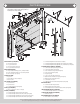
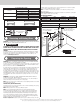
Parts Breakdown G10. NOTE: The illustrations shown on this page are general representations of the door parts. Each specific door models may have unique variations. G9. H3. G8. G7. G2. G2. F1. G3. G1. A1. G7. G10. H2. D2. G4. D1. G8. G4. E1. D1. D3. G5. E2. A2. G6. C1. G5. D1. D2. A1. A2. F6. C2. D3. F2. F4. H3. F3. C2. F6. F1. F7. G9. I1. C3. B3. F4. B2. A2. B1. A4. K1. A1. J1. H1. F7. A3. J1. F5. F2. F5. F3. I1. A. Track Rollers (As Required): A1.
Pre-Installation Important Safety Instructions Tools Required Definition of key words used in this manual: • Power drill • Drill bits: 1/8”, 3/16”, 9/32”, 7/16”, 1/2” • Ratchet wrench • Socket driver: 7/16” • Sockets: 7/16”, 1/2”, 9/16”, 5/8” WARNING Indicates a potentially hazardous situation which; if not avoided, could result in severe or fatal injury. Caution: Property damage or injury can result from failure to follow instructions. Important: Required step for safe and proper door operation.
Track roller carriers (as required) Cable drums RH/LH door. Sections are stamped for identification, #1, #2, #3, and #4 (#4 only on four section high doors). The stamp, located on each side of the sections identifies the stacking sequence. The sequence is always determined by #1 being the bottom section to #3 or #4 being the highest top section. If the stamp on the section is illegible, refer to the section side view illustration.
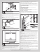
for tracks, springs, etc. to allow the door to open properly. If the door is to be motor operated, 2-1/2” (64 mm) of additional headroom is required. Note: 6” low headroom conversion kit is available for 12” radius only. Contact your local Wayne-Dalton dealer. Backroom requirement: Backroom is defined as the distance needed from the opening back into the garage to allow the door to open fully.
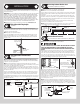
Fully Adjustable Flag Angles Side view bottom section Tools: None NOTE: If you have a wall angle track assembly or if you already have flag angles preattached to the vertical tracks, skip this step. Refer to Package Contents / Parts Breakdown, to determine if you have flag angles. Note: Flag angles are right and left handed.
(B) Locate the left hand bottom corner bracket. Align the bottom corner bracket horizontally with the bottom edge of the bottom section and also align the bottom corner bracket vertically with the left bottom edge of the bottom section. Using the bottom corner bracket as a template, mark and pre-drill (4) 9/32” diameter holes through the bottom section, as shown. Attach the bottom corner bracket to the bottom section using (4) 1/4” - 20 x 2-1/4” carriage bolts and (4) 1/4” – 20 flange hex nuts, as shown.
Single graduated end hinge with short stem track roller Double graduated end hinge with long stem track roller (4) 1/4” - 14 x 1” Lag screws (2) 1/4” - 20 x 2 1/4” Carriage bolts and (2) 1/4” - 20 Flange hex nuts or (2) 1/4” - 20 x 1-3/8” bolts Tandem roller Typical section shown.
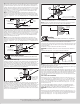
If the bottom section was shimmed to level it, the vertical track on the shimmed side must be raised the height of the shim. Position the left hand vertical track assembly / wall angle track assembly over the track rollers of the bottom section. Make sure the counterbalance lift cable is located between the track rollers and the door jamb. Drill 3/16” pilot holes into the door jamb for the lag screws.
deep. Important: Push & hold the hinge leafs securely against the sections while securing with appropriate fasteners. There should be no gap between the hinge leafs and the sections.
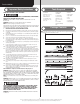
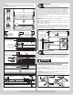
3/8”-16 x 3/4” Truss head bolt 3/8”-16 Hex nut 3/8”-16 Hex nut Horizontal track angle Horizontal track Flag angle Horizontal track Upper slots Lower slots 3/8”-16 x 3/4” Truss head bolt Adjusting Top Fixtures (2) 3/8”-16 Hex nuts Lower slots 16 Top fixture slide(s) (3) 5/16” x 1-5/8” Lag screws Horizontal track angle Center Bracket Tools: Step ladder, Power drill, 7/16” Socket driver, 1/4” Torx bit, Level, NOTE: Refer to the Package Contents and or Parts Breakdown to determine if your door c
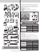
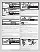
red. DO NOT identify right and left hand by the set screw color. Slide the center bracket bushing onto the torsion shaft followed by the torsion springs, cable drums and drum spacers (if required). IMPORTANT: The center bracket bushing, torsion springs, cable drums and drum spacers (if required) must be positioned, as shown. With assistance, pick up the torsion spring assembly and slide one end of the torsion shaft through one end bearing bracket. Lay the middle of the torsion shaft into the center bracket.
Black cable drum (right hand side) Drum spacer (as required) Coupler halves Set screws and Lock nut Center coupler assembly (3) 3/8” - 16 x 1-3/4” Hex head screws and (3) 3/8” - 16 Nylon hex lock nut Torsion keyed shaft Coupler halves Center bearing Red cable drum (left hand side) Left hand wound, black winding cone (right hand side) Set screws and Lock nut Center bearing Right hand wound, Key red winding cone (left hand side) Drum spacer (as required) (2) 3/8”-16 Nuts Key Coupler halves assembl
over-wound, carefully remove the locking pliers from the torsion shaft and vertical tracks. Adjustments to the number of turns stated may be necessary. If door rises off floor under spring tension alone, reduce spring tension until door rests on the floor. If the door is hard to rise or drifts down on its own, add spring tension. NOTE: An unbalanced door such as this can cause garage door opener operation problems.
tension until door rests on the floor. If the door is hard to raise or drifts down on its own, add spring tension. A poorly balanced door can cause garage door operator operation problems. To adjust spring tension, fully close door. Apply vice grips to track above third track roller. Insert a winding rod into the winding cone. On single spring doors, counterbalance lift cable tension must be maintained by placing vice grips on torsion shaft before loosening set screws in the winding cone.
Torsion spring tag(s) (one per spring) HIGH SPRING TENSION CAN CAUSE SERIOUS INJURY OR DEATH. WARNING DRILLING, SAWING, SANDING OR MACHINING WOOD PRODUCTS GENERATES WOOD DUST, A SUBSTANCE KNOWN TO THE STATE OF CALIFORNIA TO CAUSE CANCER. AVOID INHALING WOOD DUST OR USE A RESPIRATOR OR OTHER SAFEGUARDS FOR PERSONAL PROTECTION. DO NOT REMOVE, COVER OR PAINT OVER THIS LABEL. PRODUCT USER SHOULD INSPECT THIS LABEL PERIODICALLY FOR LEGIBILITY AND SHOULD ORDER A REPLACEMENT FROM THE DOOR MANUFACTURER AS NEEDED.
Optional Installation WARNING Door Arm Hookup Tools: Needle nose pliers Do not install pull down rope on doors with operators. Children may become entangled in the rope causing severe or fatal injury. At the center of the top section, measure horizontally from the top of center hinge to the bottom of strut. Using that dimension, measure and cut (2) pieces of perforated angles. Assemble the (2) pieces together using (2) 3/8” bolts and nuts (supplied by others).
Maintenance Before you begin, read all warning labels affixed to the door and the installation instructions and owner’s manual. When correctly installed, your Wayne-Dalton door will operate smoothly. Always operate your door with controlled movements. Do not slam your door or throw your door into the open position, this may cause damage to the door or its components. If your door has an electric opener, refer to the owner’s manual to disconnect the opener before performing manual door operation below.
3. Lubrication: The door should open and close smoothly. Ensure the door track rollers are rotating freely when opening and closing the door. If track rollers do not rotate freely, clean the door tracks, removing dirt and any foreign substances. Clean and lubricate (use a non-silicon based lubricant) graduated end hinges, steel track rollers, spring(s) and bearings. DO NOT lubricate plastic idler bearings, nylon track rollers, door track.
Warranty Limited warranty Model 7100 Series Subject to the terms and conditions contained in this Limited Warranty, Wayne-Dalton (“Manufacturer”) warrants the sections of the door, against defects in material and workmanship, for a period of ONE (1) YEAR from the time of delivery provided: i) (i) The interior and exterior surfaces, as well as all edges of the wood door(s) are properly finished according to the Manufactures Maintenance and Painting Instructions and finish manufacturer’s instructions.
Covered by one or more of the following Patents; 5,408,724; 5,409,051; 5,419,010; 5,495,640; 5,522,446; 5,562,141; 5,566,740; 5,568,672; 5,718,533; 6,019,269; 6,089,304; 6,644,378; 6,374,567; 6,561,256; 6,527,037; 6,640,872; 6,672,362; 6,725,898; 6,843,300; 6,915,573; 6,951,237; 7,014,386; 7,036,548; 7,059,380; 7,121,317; 7,128,123; 7,134,471; 7,134,472; 7,219,392; 7,254,868. Canadian: 2,384,936; 2,477,445; 2,495,175; 2,507,590; 2,530,701; 2,530,74; 2, 2,532,824. Other US and Foreign Patents pending.