
User Manual
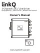


Introduction
Welcome to Wāvtech, exceptional mobile audio integration products for audiophiles. Our products are
engineered to provide a truly remarkable listening experience. Built for the professional installer, our
OEM integration and signal processor models are simply the best solution available for unlimited sound
system upgrades while retaining the factory receiver.
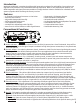
ΠPower Indicator: This red LED indicates when the linkQ is powered on. Once illuminated, there will be
a short delay before audio signal output is enabled. During initial power connections, it may illuminate
for a brief period.
Ground Jumper: For selecting between chassis, isolation or 200Ω for the internal audio signal ground.
Chassis ground is the default setting and ideal for most applications due to the differential input
stage. In the rare case there is system noise present after all other installation countermeasures,
changing this jumper to ISO or 200Ω may reduce or eliminate the noise.
Ž Power Supply Terminal: For +12V battery, chassis ground, remote input and remote output wire
connections. A minimum of 18AWG wire is recommended for power and ground connections. Always
protect the +12V power wire with a 1-amp fuse.
Speaker Level Input Terminal: For left and right channel speaker level (a.k.a. high level) connections to
the source. Input signals ranging from 2Vrms to 20Vrms will produce up to 10Vrms RCA output from
maximum to minimum gain. For factory amplifiers with more than 20Vrms signal or if the linkQ’s
output is too high for the connected aftermarket amplifier(s) with all gains at minimum, internal
jumpers (labeled 20V/40V) are available to reduce the input sensitivity range by half (-6dB) for 4Vrms
up to 40Vrms.
Clipping Indicator: This yellow LED indicates when the output signal is at maximum level before
distortion (clipping) occurs. It will be dimly lit just before the onset of clipping, and full bright at
clipping. Since the linkQ can produce up to 10Vrms output before clipping, it is likely that gain will
need to be reduced below the illumination point to match your amplifier(s) maximum input capability,
optimize source volume range or compensate for any equalization applied after initial gain setting.
‘ Gain Adjustment: This adjustment is for matching the output signal level of the linkQ with the
maximum unclipped signal range provided by your source and the maximum input capability of your
amplifier(s). Follow proper gain setting procedures to ensure optimum source volume range with
minimum chance for clipping at any point in the signal chain. Aside from music, a -10dBfs sine wave
tone at a frequency not affected by any crossovers may also be used for the tuning process to ensure
proper headroom and gain overlap for typical music recording levels.
’ Bass EQ: This section provides adjustments for a single paragraphic EQ band, which allows tuning
flexibility for differences between vehicles and sound systems to optimize bass performance.
“ Boost: Sets the amount of boost applied at the center frequency (Fc), adjustable up to +12dB.
” Frequency: Sets the center frequency (Fc) of the EQ band, adjustable from 30Hz to 80Hz.
• EQ On/Off: This switch activates or bypasses the internal equalization circuit (default setting is off).
Connections & Functions
Features
Ÿ 2-Channel Line Output Converter or Line Driver
Ÿ Remote Level Control
Ÿ Adjustable Paragraphic Bass EQ
Ÿ Differential Balanced Inputs
Ÿ Low Impedance Outputs
Ÿ Variable Gain Adjustment with Clip LED
Ÿ Auto Turn-On via DC-Offset or Audio Signal Detect
2
Ÿ Generated +12V Remote Output
Ÿ OEM Load Detect Compatible
Ÿ Selectable Ground Isolation
Ÿ Locking Detachable Power/Speaker Terminals
Ÿ Panel Mount RCA Jacks
Ÿ Compact Aluminum Chassis
Ÿ Detachable Mounting Tabs
Œ
Ž
‘
’
“ ”
•