
Specifications

Appendix A – TAP Interface Specifications - 9
Appendix A – TAP Interface Specifications
This appendix is included for those who want to develop their own paging control software or add an interface for
the SPS-5 Paging System to their existing software applications..
A simple definition of the TAP protocol is that the TAP protocol normally requires a connect and disconnect process
and normally assumes that the Host system maintains a database of pager reference numbers called IDs, and that the
paging system maintains a database of all paging parameters associated with each ID. The TAP interface supports
paging messages up to 244 characters in length. The actual maximum length of transmitted messages in the
WaveWare TAP interface is 245 minus the ID field length. With an ID value of 5, you can transmit up to 245
characters per message. With an ID value of 1233425120, you can transmit up to 235 characters per message.
The TAP specifications are maintained by PCIA (Personal Communications Industries Association). The formal TAP
specification can be obtained via the Internet at http://www.pcia.com.
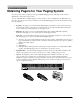
To configure your SPS-5 Paging System to use the TAP paging protocol, you may be required to configure the DIP
switch bank in the paging encoder. Please refer to Appendix B – DIP Switch Settings, for details on configuring
communication protocols. As a quick reference, a typical DIP switch setting for the TAP interface is all 8 switches in
the ON position, which tells the system to operate in TAP interface mode, with communication parameters of
9600N81, hardware flow control, and verbose responses from the encoder.
Your SPS-5 Paging System typically communicates with a PC or other host device via RS-232 at 9600 Baud, 8 data bits
and 1 stop bit. The eighth data bit is ignored (no parity). You can configure the paging system for other serial
communication parameters. Please refer to Appendix B – DIP Switch Settings, for details on serial communication
parameters.
The paging encoder maintains an input buffer which can receive commands from the PC while a page is being
transmitted. The input buffer should be able to contain approximately ten paging messages before getting full.
When a command is received from the PC, the paging system responds with a message that includes error messages
if the command was not understood or not properly transmitted. The first three digits of each paging system
response conforms to the response codes defined in the TAP v1.8 specification. See Appendix D – TAP Response
Codes for a listing of the response codes.
The paging encoder encodes paging messages into POCSAG paging format and transmits the encoded paging
message. If the Carrier Detect function is enabled, transmissions will be delayed while interfering signals are
detected.
Control characters recognized by the paging system in TAP protocol mode include:
CARRIAGE RETURN <CR> $0D
START OF TEXT <STX> $02
END OF TEXT <ETX> $03
END OF TRANSMISSION <EOT> $04
SUBSTITUTE <SUB> $1A
ESCAPE <ESC> $1B
Control characters generated by the SPS-5 Paging System in TAP protocol mode include:
LINE FEED <LF> $0A
CARRIAGE RETURN <CR> $0D
ACKNOWLEDGE <ACK> $06
NEGATIVE ACKNOWLEDGE <NAK> $15
ABANDON TRANSACTION <RS> $1E
ESCAPE <ESC> $1B
END OF TRANSMISSION <EOT> $04
XON <XON> $13
XOFF <XOFF> $11