
Specifications

5
Paging System Installation
Your SPS-5 Paging System includes a Black 8”x8”x2” Transmitter Unit, a “Rubber Duck” Antenna, a Mounting Kit, a
6’ Serial Cable, and a Power Adapter. Refer to the diagram on the following page. To install the paging system,
perform the following steps:
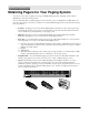
1. Attach the “Rubber Duck” Antenna to the Transmitter Unit. In normal paging operations, the paging
transmitter antenna should be oriented in a vertical position to maximize the paging range.
Note: Do not attempt to operate the paging system without the antenna connected to the paging transmitter, as
damage to the paging transmitter may occur.
2. Open the paging system enclosure, 2 screws 1 ea. top and bottom. Three screws are provided for the
mounting of paging. Find suitable location for installation and mount.
3. Plug the Power Adapter Plug into the 2 conductor white power interface connector.
4. Plug the serial cable into the DB9 female connector on the Transmitter Unit. Tighten connector screws.
5. Plug the Power Adapter into a 110 VAC power outlet. The red colored PWR/BAT LED indicator on the
Transmitter Unit should be illuminated when power is properly applied.
6. Program the pager database, if required, using WaveWare Paging Encoder Setup software, which is
available from the WaveWare web site at http://www.wirelessmessaging.com
7. If you are using a PC as a Host Device, load paging control software, such as WaveWare software, on the
PC and configure it to operate with your SPS-5 Paging System. Make sure the proper serial port settings are
defined. The green colored TX LED indicator on the Transmitter Unit should illuminate during a paging
transmission. If the Carrier Detect function is enabled, you may see the green colored CD LED indicator
temporarily illuminate prior to some paging transmissions, if a carrier signal is detected from a nearby
transmitter at the same frequency as your SPS-5 Paging System.