
Specifications


Appendix H – COMP2 Interface Specifications - 20
Appendix H – COMP2 Interface Specifications
This appendix is included for those who want to attach the SPS-5 Paging System to existing systems that output
simplified paging system control commands. The COMP2 protocol is designed to emulate one of the operational
modes of the Motorola People Finder™ paging system.
A simple definition of the COMP2 protocol is that the COMP2 protocol allows a message formatted as
PagerID<CR>Message<CR> to cause the Message to be delivered to the associated PagerID defined in the SPS-5
Paging System's pager database. The COMP2 interface supports paging messages up to 253 characters in length.
The total length of the control string, including <CR> and <LF> characters, cannot exceed 256 characters. The
PagerID field can be from 1 to 10 characters in length. PagerID field lengths from 5 to 10 digits are assumed to be
Extended Pager IDs (See Appendix E – Extended Pager ID Processing).
To configure your SPS-5 Paging System to use the COMP2 paging protocol, you may be required to configure the
DIP switch bank in the paging encoder. Please refer to Appendix B – DIP Switch Settings, for details on configuring
communication protocols. As a quick reference, the DIP switch setting for the COMP1 interface is switches 6 and 7
in the OFF position and all other switches in the ON position. This tells the system to operate in COMP2 interface
mode, with communication parameters of 9600N81, with hardware flow control.
Your SPS-5 Paging System typically communicates with a PC or other host device via RS-232 at 9600 Baud, 8 data bits
and 1 stop bit. The eighth data bit is ignored (no parity). You can configure the paging system for other serial
communication parameters. Please refer to Appendix B – DIP Switch Settings, for details on serial communication
parameters.
The paging system maintains an input buffer, which can receive commands from the PC while paging messages are
being transmitted. The paging encoder encodes paging messages into POCSAG paging format and transmits the
encoded paging message through the internal radio transmitter. If the Carrier Detect function is enabled,
transmissions will be delayed while interfering signals are detected.
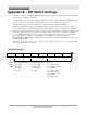
Control characters recognized by the paging encoder in COMP2 protocol mode include:
CARRIAGE RETURN <CR> $0D
LINEFEED <LF> $0A
DELETE <DEL> $7F or $FF
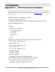
Control characters generated by the SPS-5 Paging System in COMP2 protocol mode when software flow control
mode is active include:
CARRIAGE RETURN <CR> $0D
XON <XON> $13
XOFF <XOFF> $11
ABANDON TRANSACTION <RS> $1E
In COMP2 interface protocol, the SPS-5 Paging System does not provide feedback response signals on the serial
port, other than flow control signals. COMP2 can operate as either a one way (simplex) protocol or a two way
(duplex) protocol. The COMP2 operation is as follows:
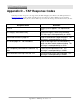
The SPS-5 Paging System in COMP2 mode is controlled using control strings formatted as follows:
Single Message Example:
PagerID<CR>Message<CR>
Tone/Vibe Only Example:
PagerID<CR><CR>
Multiple Message Example: