
Specifications


Appendix G – COMP1 Interface Specifications - 18
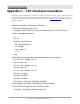
Appendix G – COMP1 Interface Specifications
This appendix is included for those who want to attach the SPS-5 Paging System to existing systems that output
raw data or simple data strings that are normally used in printing status logs on serial printers. The COMP1 protocol
is designed to emulate one of the operational modes of the Motorola People Finder™ paging system.
A simple definition of the COMP1 protocol is that the COMP1 protocol allows raw ASCII data to be sent to all pagers
in the SPS-5 Paging System's pager database. The COMP1 interface supports paging messages up to 255 characters
in length.
To configure your SPS-5 Paging System to use the COMP1 paging protocol, you may be required to configure the
DIP switch bank in the paging encoder. Please refer to Appendix B – DIP Switch Settings, for details on configuring
communication protocols. As a quick reference, the DIP switch setting for the COMP1 interface is switch 7 in the
OFF position and all other switches in the ON position. This tells the system to operate in COMP1 interface mode,
with communication parameters of 9600N81, with hardware flow control.
Your SPS-5 Paging System typically communicates with a PC or other host device via RS-232 at 9600 Baud, 8 data bits
and 1 stop bit. The eighth data bit is ignored (no parity). You can configure the paging system for other serial
communication parameters. Please refer to Appendix B – DIP Switch Settings, for details on serial communication
parameters.
The paging system maintains an input buffer, which can receive commands from the PC while paging messages are
being transmitted. The paging encoder encodes paging messages into POCSAG paging format and transmits the
encoded paging message through the internal radio transmitter. If the Carrier Detect function is enabled,
transmissions will be delayed while interfering signals are detected.
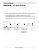
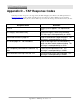
Control characters recognized by the paging encoder in COMP1 protocol mode include:
CARRIAGE RETURN <CR> $0D
LINEFEED <LF> $0A
Control characters generated by the SPS-5 Paging System in COMP1 protocol mode when software flow control
mode is active include:
XON <XON> $13
XOFF <XOFF> $11
In COMP1 interface protocol, the SPS-5 Paging System does not provide feedback response signals on the serial
port, other than flow control signals. COMP1 is a one way (simplex) protocol.
The COMP1 operation is as follows:
When incoming data is detected on the serial port, one of three things will happen: 1) A carriage return character is
detected in the datastream, 2) a time period of approximately 10 seconds elapses after receipt of the last character on
the serial port, or 3) 256 characters or more accumulate in the serial port input buffer. If any of these three events
occur, the paging system will strip any carriage return and linefeed characters and transmit the remainder of the
datastream to all pagers defined in the encoder's pager database.
If the serial port input buffer becomes filled with greater than 600 characters, the paging system will output either a
hardware or software flow control response, depending upon how DIP switch 1 is configured. Once the serial port
input buffer drops below 450 characters, the paging system will use flow control signals to indicate that it is no
longer busy and that additional data can be delivered to the serial port.