
Specifications


Appendix B – DIP Switch Settings - 13
Appendix B – DIP Switch Settings
You may be required to configure the DIP switch bank in the paging encoder to establish the appropriate operating
mode and serial communication parameters.
Your SPS-5 Paging System typically communicates with a PC or other host system via RS-232 at 9600 Baud, 8 data
bits and 1 stop bit. You can configure the paging system for other serial communication parameters.
The available operating modes include TAP Verbose, TAP Non-Verbose, COMP1, and COMP2.
TAP Verbose means that the paging system will include human readable messages after each paging request is
received. TAP Non-Verbose reduces the paging system human readable response to 3 digit numeric codes. The
Non-Verbose mode is useful in situations where you want to minimize the serial data throughput requirements, which
tends to allow paging messages to be delivered more quickly. Refer to Appendix A for a definition of the TAP
protocol. COMP1 means that any data received on the serial port will be sent to all pagers in the pager database.
Refer to Appendix H for a definition of the COMP1 protocol. COMP2 means that data formatted as
PagerID<CR>Message<CR> will cause the Message to be delivered to the specified PagerID. Refer to Appendix I for
a definition of the COMP2 protocol.
Independent of operating modes, you can configure the serial port baud and parity, and you can configure whether
hardware or software flow control is used.
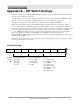
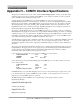
DIP Switch Settings
1 2 3 4 5 6 7 8
Flow Ctrl
1 = H/W
0 = S/W
Baud (Serial Interface)
11 = 9600
10 = 2400
01 = 1200
00 = 300
Parity (Serial Interface)
11 = None (N81)
10 = None (N81)
01 = Even (E71)
00 = Odd
Protocol
111 = TAP Verbose
110 = TAP Non-Verbose
101 = COMP1
100 = TAP Verbose
011 = TAP Verbose
010 = TAP Non-Verbose
001 = COMP2
000 = TAP Verbose
ON = 1