
User guide


CHAPTER 10 TOOLS 97
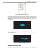
Channel Outputs Switch
e Channel Outputs toggle switch and 1–16 checkboxes are used to help assist in testing
of the rack card outputs.
If the Channel Outputs switch is ON, all the selected channel outputs on the Click 112/114
rack card or Click 104 contact closure device will be active. e LEDs that indicate an ac-
tive output channel will light up accordingly. An output will only be active when the cor-
responding box is checked.
Note
It is recommended that you disable pushing by sensors or disconnect the detection
call bus patch cord for each sensor before using this tool. Otherwise, the rack card
may be receiving conflicting calls on its other bus.
e Channel Outputs switch can be very helpful in verifying the I/O channel mapping from
the rack card outputs to the trac controller inputs. By sequentially checking boxes 1–16,
you should be able to quickly verify the mapping of each channel, even in the absence of
trac.
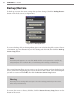
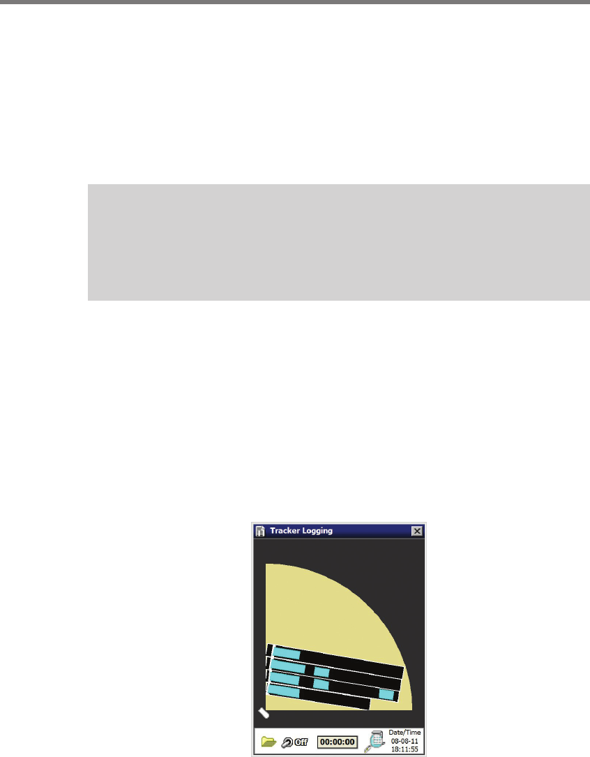
Tracker Logging
Access the Tracker Logging tool by clicking on the Tracker Logging button on the Tools
screen. is tool will allow you to log vehicle detections as they are tracked through the
sensor’s view (see Figure 10.5). is tool can be used to record trackers and replay them at
a later time for demonstration purposes.
Figure 10.5 – Tracker Logging Tool