
User guide

8 INTRODUCTION SMARTSENSOR MATRIX USER GUIDE
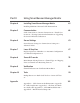
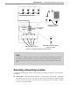
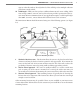
140 ft
Sensor Pole
140 ft
Figure I.3 – Corner Radar
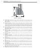
Line of sight – Position the sensor so that it will be able to detect the entire area of
interest. Avoid occlusion by installing the sensor away from trees, signs and other road-
side structures.
Detection coverage – Position the sensor so that it will be able to reach all the specied
stop bar detection zones. e sensor will oen work better if you position it so that it
tracks vehicles for several feet before the rst zone in each lane. If the sensor has a view
several feet beyond the stop bar, it is more likely to accurately detect queue dissipation.
Closest roadside – Mount the sensor on the side of the road closest to the lanes of pri-
mary interest. Always mount the sensor high enough to prevent trac from occluding
approaching vehicles.
Mounting height – A minimum height of 12 . (3.6 m) is recommended. Mounting
the sensor higher will generally improve line of sight and decrease the possibility of
occlusion.
Mounting oset – A minimum oset of 6 . (1.8 m) to the rst lane of interest is
required.
Redundant detection – It is possible to have multiple sensors monitoring the same
approach. Multiple sensors are needed when zones are spread over more than 140 .
(42.7 m).
Sensor proximity – When multiple sensors are mounted at the same intersection, in-
terference can be avoided by conguring each sensor to operate on a unique RF chan-
nel.
Departing lanes – ere is usually no need to view trac in departing lanes or to con-
gure departing lanes. However, if they are congured, then the stop bar should not
be congured.
Suspended electrical cables – e sensor is designed to work in the presence of sus-
pended power lines and other electrical cables. However, these cables should be at least
10 . (3 m) away from the front of the sensor.
Neighboring structures and parallel walls – e sensor should not be mounted with