
User guide
86 CHAPTER 8 ZONES & CHANNELS
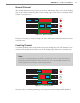
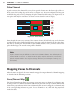
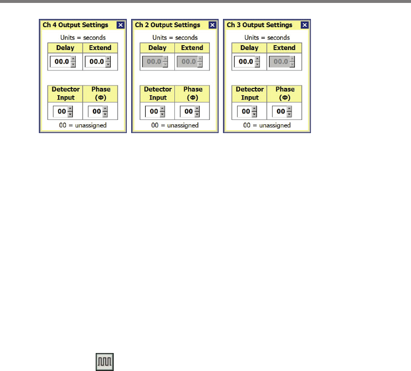
Figure 8.12 – Output Settings (Normal, Counting, Pulse)
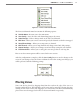
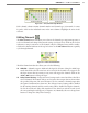
Detector Input – e Detector Input number provides a way for you to map inputs to
the intersection phase in the controller. By default, the Detector Input will be set to
“00;” if the input is le at “00,” then it is unassigned. is setting is for reference pur-
poses only and does not actually change the sensor.
Phase – Since the SmartSensor Matrix is capable of monitoring more than one phase,
this setting allows you to enter the phase number that most closely represents the phase
the sensor is monitoring. By default, the Phase will be set to “00;” if the phase is le
at “00,” then it is unassigned. is setting is for reference purposes only and does not
actually change sensor operation.
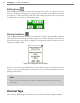
Channel Type – is drop-down list allows you to select the type of channel (Normal,
Counting or Pulse). A normal channel is presence detection; a counting channel is
a special pulse based on counting algorithms; and a pulse channel is a generic pulse
based on zone presence.
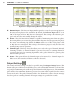
Invert – is option allows the channel output to be inverted (i.e. channel output de-
faults to on, then switches o when a vehicle is detected).
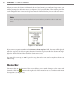
Output Settings
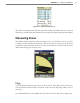
e extend and delay settings can also be specied using the Output Settings button. is
button will open a window that will allow you to select individual channels to edit and also
to specify the minimum pulse width and pulsed channel width (Figure 8.13). e minimum
pulse width is the minimum duration a presence detection will be signaled via the contact
closure rack cards. e pulsed channel width is the duration the contact closure message
lasts for a pulse or counting channel. All output settings are specied in seconds.