
User guide
84 CHAPTER 8 ZONES & CHANNELS
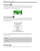
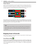
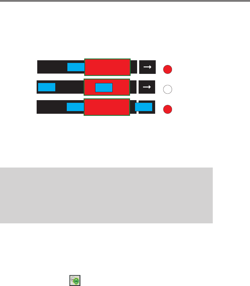
Pulse Channel
A pulse activates the channel for a very short period of time once the front edge of the ve-
hicle crosses the leading edge of the zone (see Figure 8.9). You can congure how long you
would like the pulse to be by changing the pulse channel width setting (see Figure 8.13). A
new pulse will only be sent aer a car enters a zone when the zone is empty.
Channel LED
Pulse
Channel LED
Channel LED
Figure 8.9 – Pulse Channel
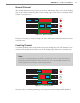
Even though the zone stays activated, the contact closure call will only stay on for the time
specied in the pulse channel width setting. You can verify the duration of the pulse chan-
nel calls by viewing the virtual LEDs in the SSMM soware. Once you have selected the
pulse channel type, the extend setting will be disabled.
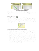
Note
A pulse channel may be dicult to view in the SSMM software. The default pulsed
channel width is 200 ms. To better view the pulse channel activation, increase the
pulsed channel width in the output settings window (see the Output Settings sec-
tion below).
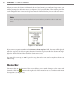
Mapping Zones to Channels
Aer the zones are placed, the zones must be mapped to output channels. Channel mapping
is described in the following sections.
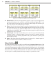
Zone/Channel Map
e Zone/Channel map allows you to map or un-map zones to channels (see Figure 8.10).
To map a zone to a channel, determine which zone you want to map to which channel and
click on the gray indicator in the Zones/Channels table. A zone is mapped to a channel only
if the corresponding indicator is green. To see Channels 9–16, click and drag anywhere
inside the table.