
User guide

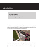
INTRODUCTION SMARTSENSOR MATRIX USER GUIDE 7
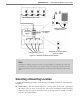
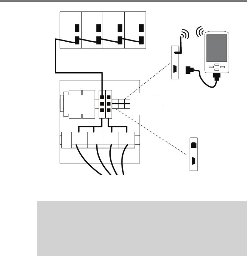
Control Bridge to Rack Cards
Control Bridge to Sensors
Configuration Toolkit
(attach to T-bus)
Control Bridge
on T-bus
AC Power
Conversion
Option
Remote IP Connection Option
(attach to T-bus)
Figure I.2 – SmartSensor Matrix System Options
Note
SmartSensor Matrix systems provide a control bridge to manage all connected
SmartSensor and Click devices. The control bridge is completely separate from the
dedicated channels used for communication of contact closure detection calls in real
time.
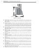
Selecting a Mounting Location
Consider the following guidelines when selecting a mounting location for each SmartSen-
sor Matrix:
Corner radar – e SmartSensor Matrix is a corner radar device with a panoramic
90°, 140-. (42.7-m) view (see Figure I.3). e sensor’s mounting location should be
selected so that all stop bar detection zones on an approach are within a 6–140-.
(1.8–42.7-m) radial distance.