
User guide


64 CHAPTER 6 SENSOR SETTINGS
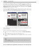
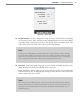
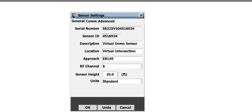
Figure 6.1 – Serial Settings Window
e General tab contains the following elds:
Serial Number – Contains the sensor serial number and cannot be edited.
Sensor ID – Contains the ID used to uniquely identify all sensors on a multi-drop bus.
is ID is the last seven digits of the sensor’s serial number and cannot be edited.
Description – Allows you to enter a description for each sensor. Limited to 64 charac-
ters.
Location – Allows you to enter the intersection location of the sensor. Limited to 64
characters.
Approach – Allows you to enter information about the direction of trac the sensor is
detecting (e.g. NB, SB, EB, WB). Limited to 32 characters.
RF Channel – Lets you set which one of the eight radio frequency channels the sensor
is using. Using multiple sensors in close proximity will require each sensor to be set
to a dierent RF channel (see the introduction for more information about mounting
the sensor).
Sensor Height – e height of the sensor in feet. is value aects the sensor’s detec-
tion algorithms. Entering an approximate height measurement for the sensor allows
detections to be placed correctly on the roadway.
Units – Allows sensor height, zone dimensions and road objects to be viewed in metric
mode rather than standard units.
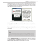
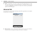
Comm Sensor Settings
e Comm tab allows you to change the response delay, and other settings (see Figure 6.2).