
User guide
CHAPTER 5 COMMUNICATION 53
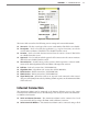
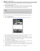
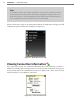
Figure 5.4 – Sensor Info Screen
e Sensor Info screen lists the following sensor settings and version information:
Sensor ID – e last seven digits of the sensor serial number. is eld is not editable.
Description – Used to describe the application (e.g. stop bar detection); can also be
used for GPS coordinates. is eld is not editable from this screen.
Location – Used to describe the intersection where the sensor is located. is eld is
not editable from this screen.
Approach – Used to indicate which approach of the intersection the sensor monitors.
is eld is not editable from this screen.
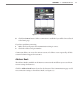
Sensor Version – Overall sensor product version, which represents a released combi-
nation of the DSP, Algorithm, FPGA and FPAA subcomponent versions.
DSP Rev – DSP code version date (YYYY-MM-DD).
Algorithms Rev – Algorithm code version date (YYYY-MM-DD).
FPGA Version – FPGA version date (YYYY-MM-DD).
FPAA Version – FPAA version date (YYYY-MM-DD).
Signal Rack Cards – When the switch is on, any rack cards connected to this sensor’s
data port will identify themselves by ashing a blink sequence on the main menu LEDs
of the rack card.
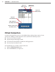
Internet Connection
e SmartSensor Matrix can be connected to the Internet, allowing access to the sensor
from anywhere with Internet access. e following is a list of ways to connect the SmartSen-
sor Matrix to the Internet:
Serial to Ethernet Converter – e SmartSensor Matrix can be connected to a local
area network (LAN) by using a Click 301 serial to Ethernet converter.
Serial to 802.11b Wireless – e SmartSensor Matrix can be connected using a Click