
User guide


40 CHAPTER 3 CONTACT CLOSURE COMMUNICATION
NEMA TS2, 2070 and other advanced trac cabinet systems usually allow soware pro-
gramming of the detector card channel outputs to trac phases via a channel-to-phase
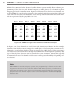
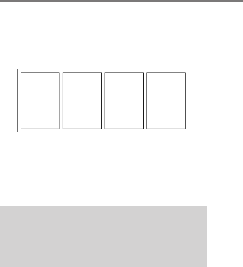
mapping grid in the controller menu. Figure 3.12 illustrates how the detector channels 1 to
16 of a NEMA TS-2 rack can be assigned to the standard eight phases using four Click 114
cards. e rack card slots are numbered across the top and the controller’s detection chan-
nels are represented by the gray labels C1–C16.
C1
↓
Φ
1
C2
↓
Φ
6
C3
↓
Φ
6
C4
↓
Φ
6
C5
↓
Φ
5
C6
↓
Φ
2
C7
↓
Φ
2
C8
↓
Φ
2
C9
↓
Φ
3
C10
↓
Φ
8
C11
↓
Φ
8
C12
↓
Φ
8
C13
↓
Φ
7
C14
↓
Φ
4
C15
↓
Φ
4
C16
↓
Φ
4
Slot 1 Slot 2 Slot 3 Slot 4 Slot 5 Slot 6 Slot 7 Slot 8
Figure 3.12 – NEMA TS-2 Type 1 Rack Channel to Trac Phase Example
In Figure 3.12, four channels are used from each SmartSensor Matrix. In this example,
channel 1 from the rst sensor is mapped to trac phase 1 (le-turn phase on main street).
Channels 2, 3 and 4 from the rst sensor are mapped to trac phase 6. is represents a
case where detections from three through-movement lanes are brought in separately. is
type of lane-by-lane detection can be benecial in some situations. Wavetronix typically
recommends the use of 4-channel cards because it oers greater exibility of signaling con-
tact closures.
Note
With NEMA TS1 and other legacy systems, the programming is often done via a wir-
ing panel on the side of the controller cabinet. With wired systems, you will need to
verify that the wiring on the detector programming panel provides the proper map-
ping from the rack channel outputs to the controller input wires dedicated for ф1–ф8
detector calls.