
User guide


CHAPTER 3 CONTACT CLOSURE COMMUNICATION 39
menu option.
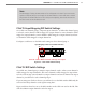
4 Press and hold the mode switch to cycle through the submenu. e Level 2 LEDs will
light to indicate that the device is cycling though all conguration options.
5 Release the mode switch once the desired conguration option is reached.
6 Quickly press and release the mode switch to select the current conguration option.
e device will exit Menu mode, and either the selected function will run or the se-
lected conguration will be set and saved to the device.
Channel Mapping
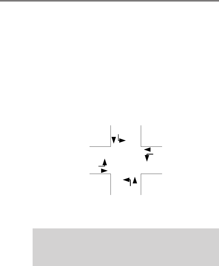
Once the Click 104/112/114 devices are installed, make sure that each detector rack channel
is properly mapped to the correct trac phase in the trac controller. e general NEMA
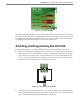
standard for 8-phase numbering is presented in Figure 3.11. Many intersections will not
have eight phases, and in some cases they may not even follow the NEMA convention.
Check the plans in the trac signal cabinet to verify how the phases are numbered at each
intersection.
2
5
1
6
4
7
8
3
Figure 3.11 – Standard NEMA 8-phase Number Scheme
Phases 1, 2, 5 and 6 are oen used for the “main” street, and phases 3, 4, 7 and 8 are oen
used for the “side” street as shown in Figure 3.11.
Note
Chapter 10 contains a section about Rack Card Tools which explains how the channel-
to-phase mapping can be verified with or without the sensors installed.
Since each Matrix sensor oen detects both the le-turn phase and the through-movement
phase for a single approach, the associated rack card will have oen have channels that cor-
respond to one of the following phase (ф) pairs: ф2 and ф5; ф6 and ф1; ф4 and ф7; ф8 and
ф3.