
User guide


38 CHAPTER 3 CONTACT CLOSURE COMMUNICATION
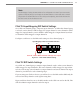
3 If needed, daisy-chain multiple Click 104 devices together by utilizing both RJ-11 jacks
on each device’s faceplate.
Click 104 LEDs
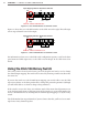
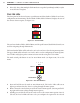
e front panel of the device features a push-button and three banks of LEDs for on-device
conguration and monitoring. e rst bank of LEDs, labeled Channel, displays the state of
the contact closure outputs (see Figure 3.9).
1 2 3 4
Channel
Menu
PWR OK TD RD
Figure 3.9 – Click 104 LEDs
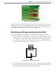
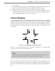
e two lower banks of LEDs, labeled Menu, and the push-button, labeled Mode Switch, are
used for navigating through Menu mode.
e lower bank of LEDs will be referred to as Level 1 and is used in selecting menu options.
e upper bank will be referred to as Level 2 and is used in conguring the menu options.
Level 2 LEDs only light up when a menu selection is made using the Level 1 LEDs.
e mode switch push-button is used to enter Menu mode (see Figure 3.10). To use the
menu:
Mode Switch
Menu
PWR
OK TD RD
1 2 3 4
Level 1
Level 2
Figure 3.10 – Click 104 LED Menu
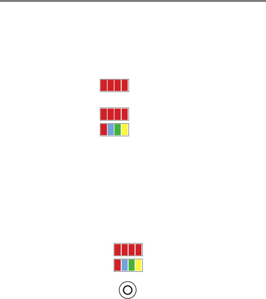
1 Press and hold the mode switch to enter Menu mode. e Level 1 LEDs will start to
light up to indicate that the device is cycling through all menu options.
2 Release the mode switch when you reach the desired menu option. (Pressing and hold-
ing again will resume cycling through menu options.)
3 Quickly press and release the mode switch to select the current menu option. Once it’s
selected, the Level 2 LEDs will start to let you congure the options for the selected