
User guide


CHAPTER 3 CONTACT CLOSURE COMMUNICATION 37
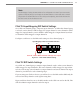
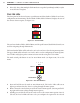
Detection
Channel
Menu Level 2
Menu Level 1
Mode Switch
Figure 3.7 – Click 112/114 Menu
Normally, a SmartSensor Matrix sensor will send 10 contact closure messages each second.
If a rack card does not receive communications from a sensor within 10 seconds, the rack
card will go into fail-safe mode and all of the contact closures will be activated and the cor-
responding detection channel LEDs on the faceplate will turn on.
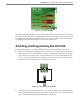
Attaching and Programming the Click 104
Use the following steps to set up the DIN rail contact closure module for each sensor:
1 Mount the Click 104 on a DIN rail over a T-bus connector. is connects the device’s
control bus (bus 2) to the installation’s shared communication bus; you can connect
your computer to another device on this shared bus, such as the Click 305 USB con-
verter, to access the Click 104 to congure it using Click Supervisor. Mounting the
Click 104 on the T-bus also connects it to the power source.
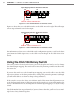
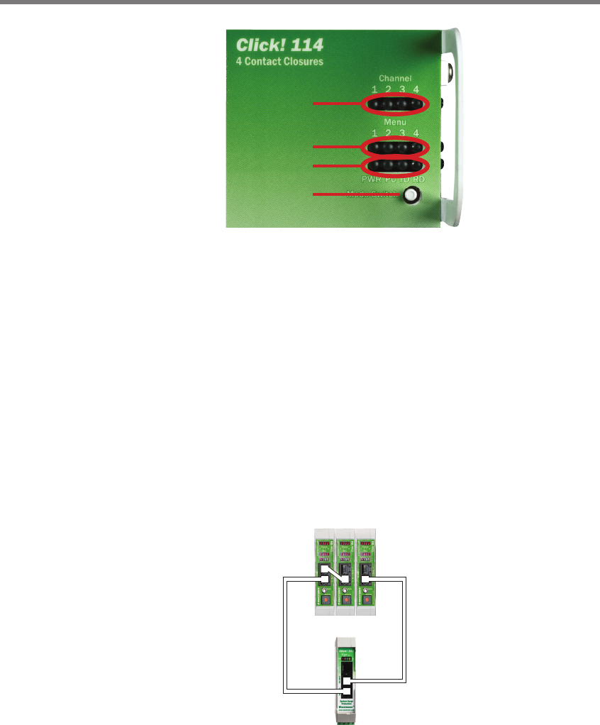
Figure 3.8 – Wiring the Click 104 Module
2 Send detection data to the data bus (bus 1). Connect a Click 222 to the Click 104 by
connecting jumper cables from the RJ-11 jacks on the faceplate of the Click 222 to the
RJ-11 jacks on the faceplate of the Click 104 (see Figure 3.8).