
User guide


36 CHAPTER 3 CONTACT CLOSURE COMMUNICATION
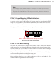
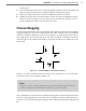
4 Connect a 6-. (1.8-m) patch cord from the Click 222 RS-485 B port to a bus 1 port on
another rack card.
5 If you are using Click 112 cards, use an 6-in. (15-cm) patch cord to share bus 1 between
cards dedicated to the same sensor. Also, congure one card to use Matrix channels 1
and 2 and congure the other card to use Matrix channels 3 and 4. If you have more
than two sensors in your system, repeat steps 2–4 to connect bus 1 for all remaining
rack cards.
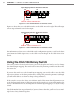
6 Connect a 5-. (1.5-m) patch cord from one of the Click 222 bridge ports to bus 2 of
the rack cards.
7 Use the 6-in. (15 cm) patch cords to create a daisy-chain that shares bus 2 between all
of the rack cards. Bus 2 will be used for device conguration.
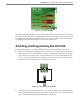
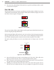
Click 112/114 LEDs
Once you have completed the wiring, check the Menu Level 1 LEDs, which have both
menu-indicating and general status–indicating functions. e list below contains informa-
tion on the general status–indicating functions of the LEDs:
PWR (red) – Indicates the device is powered.
PU (blue) – is LED is not associated with any general status function and should
remain o while the card is in normal operating mode.
TD (green) – Indicates the card is transmitting serial communication.
RD (yellow) – Indicates the card is receiving serial communications.
e red LED should be on, showing the card is powered and operating normally.
e list below contains additional information about the rest of the LEDs:
Detection Channel LEDs (red) – Indicates when a call is placed on the corresponding
contact closure output channel.
Menu Level 2 – Used for the conguration menu that is activated using the Mode
switch.
General Status (Menu Level 1) – In addition to the functions listed above, these are
used to cycle through and select options from the front panel menu.