
User guide


34 CHAPTER 3 CONTACT CLOSURE COMMUNICATION
1
2
3
4
5
6
7
8
1
2
3
4
5
6
7
8
On
O
Channel
Group
Bus 1 Bus 2
S4 S5
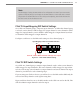
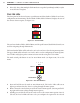
Input Mapping Switches Baud Rate Switches
Click 112 –Selects channels 1 & 2
Figure 3.4 – Click 112 DIP Switches for Channels 1 and 2
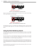
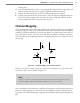
Figure 3.5 shows how to set the DIP switches on the Click 112 on the right. is will assign
sensor output channels 3 and 4 for output.
1
2
4
3
5
6
7
8
1
2
3
4
5
6
7
8
On
O
Click 112 – Selects channels 3 & 4
Channel
Group
Bus 1 Bus 2
S4
S5
Input Mapping Switches Baud Rate Switches
Figure 3.5 – Click 112 DIP Switches for Channels 3 and 4
For information on how to use other DIP switch conguration options, as well as the front
panel menu and Click Supervisor, see the Click 112/114 chapter in the Click Series User
Guide.
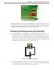
Using the Click 104 Rotary Switch
e rotary switch is located on the lower part of the faceplate and can be used to change
the channel input mapping. e switch can be twisted by inserting a small screwdriver into
the arrow slot.
If you use this switch to set the channel input mapping, you won’t be able to use the Click
Supervisor soware or the front panel menu to change this particular parameter (although
you will still be able to use them to change other parameters).
If the switch is set to 0, the device is in Soware mode. is means that all parameters are
set by the front panel menu or Click Supervisor. If the switch is set to any other number, the
device is in Hardware mode, meaning that the channel input mapping is set by the rotary
switch.
e Click 104 has four output channels; if you need more than this, you’ll need to use mul-
tiple devices daisy-chained together.