
User guide


32 CHAPTER 3 CONTACT CLOSURE COMMUNICATION
Note
See the Click 100–400 Series User Guide for complete information on how to con-
nect and configure the Click 104 DIN rail contact closure module and the Click 112/114
detector rack cards.
Each SmartSensor Matrix could potentially use up to 16 channels using a combination of
Click 104/112/114 contact closure modules. is means that a standard four-approach stop
bar detection system can be accommodated by a 64-channel detector rack.
e Click 112/114 cards can be congured using DIP switches on the circuit board, the
front panel menu on the faceplate or Click Supervisor. e Click 104 can be congured us-
ing the rotary switch, the front panel menu on the faceplate or Click Supervisor.
Using the Click 112/114 DIP Switches
e DIP switches allow you to program the baud rate and input mapping using the hard-
ware. If the Click 112/114 cards are programmed using the DIP switches, the settings can be
viewed, but not modied, using the front panel menu or Click Supervisor.
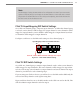
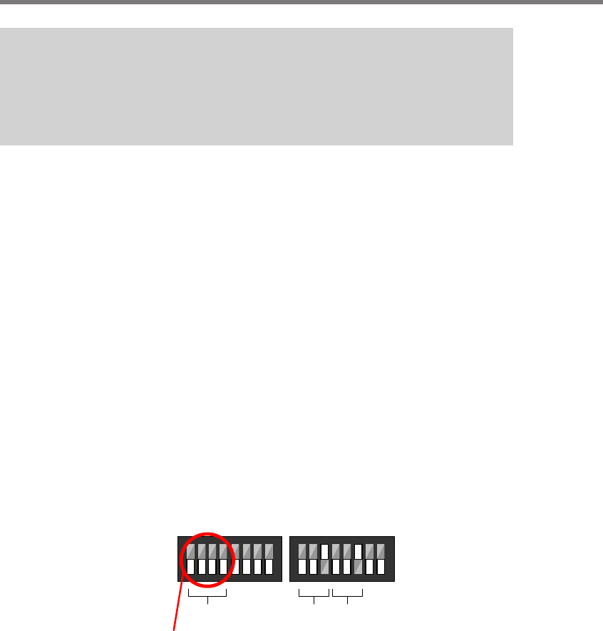
If you are planning to use either the front panel menu or Click Supervisor to program the
device settings, then you will need to rst make sure that the DIP switches are set to allow
for soware conguration; to set this, simply make sure that all relevant switches are turned
o (see Figure 3.2).
1
4
3
5
6
7
8
1
2
3
4
5
6
7
8
2
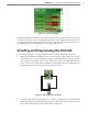
On
O
Makes channel group selection software configurable
Channel
Group
Bus 1 Bus 2
S4
S5
Input Mapping Switches
Baud Rate Switches
Figure 3.2 – DIP Switch Setting for Software Configuration Mode (left)
ere is no need to change the baud rate of the Click 112/114 cards from the factory default
of 9600 baud. e settings for the input mapping, however, will need to be set. is process
is explained in the following sections.