
User guide


CHAPTER 2 CONNECTING POWER AND SURGE PROTECTION 29
Note
Do not strip the service end of the cable until after it has been routed through con-
duit. The cable should be one continuous run without any splices.
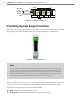
Use the steps below to land the sensor cables:
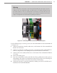
1 Aer routing your SmartSensor 6-conductor cable into the cabinet, carefully strip back
the cable jacket and shielding on the service end of the cable.
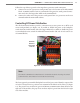
2 Open the insulation displacement connectors on the plug by inserting a small screw-
driver into each square slot and rocking it back.
3 Insert the wire leads into the bottom side of the plug-in terminal according to the color
code shown in Table 2.1 and Figure 2.8. Make sure the wires are completely inserted
in the terminal.
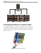
4 Close the insulation displacement connector by reinserting the screwdriver into the
square slot and rocking it forward. e plug-in terminals will automatically complete
the electrical connection. ere is no need to manually strip the insulation on the end
of each wire.
ere are two measures in place to ensure that the plugs are always returned to their correct
terminal block sections.
First, for visual conrmation, one part of the plug is blue (see Figure 2.8) and must be
visually matched up to a blue terminal block. e location of the blue piece rotates in the
dierent plugs and terminal block sections: in the rst, the rst block is blue, in the second,
the second is blue, etc.
Second, the plugs are keyed (see the blue piece in Figure 2.8) so they will only t into their
correct terminal block sections.
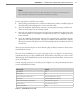
Wire Color Signal
Red (PWR) DC+
Black (GND) DC-
White with Blue stripe (485+) Control bridge 485+ (port1)
Blue (485-) Control bridge 485 - (port 1)
White with Orange stripe (485+) Data bus 485+ (port 2)
Orange (485-) Data bus 485- (port 2)
Bare metal (DRN) Drain
Table 2.1 – Cable Wiring Color Code