
User guide


28 CHAPTER 2 CONNECTING POWER AND SURGE PROTECTION
SSMatrix #2
x
x
PWR
x
x
DR N
x
x
GN D
x
x
485+
x
x
485-
x
x
485+
x
x
485-
x
OUT
x
IN
x
x
PWR
x
x
DR N
x
x
GN D
x
x
485+
x
x
485-
x
x
485+
x
x
485-
x
OUT
x
IN
SSMatrix #3
x
x
PWR
x
x
DR N
x
x
GN D
x
x
485+
x
x
485-
x
x
485+
x
x
485-
x
OUT
x
IN
SSMatrix #4
x
x
PWR
x
x
DR N
x
x
GN D
x
x
485+
x
x
485-
x
x
485+
x
x
485-
x
OUT
x
IN
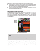
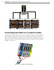
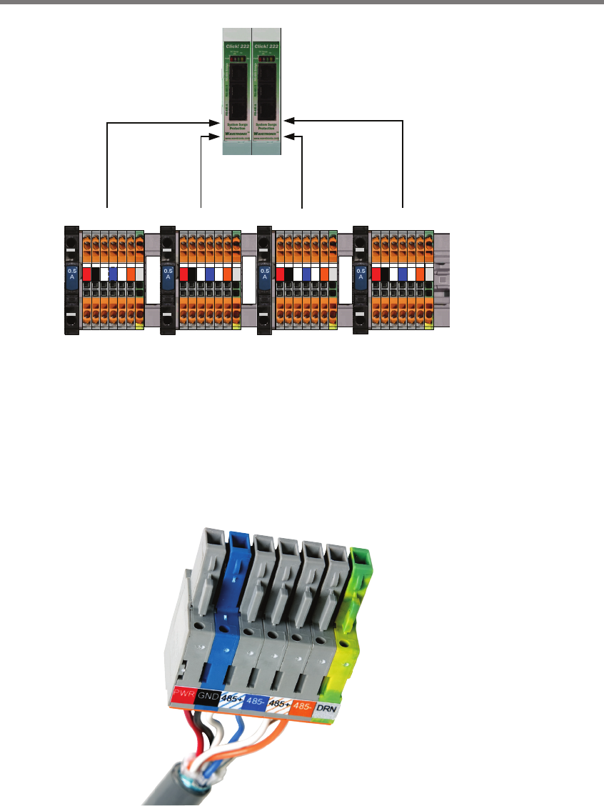
Port A & Port C Port B & Port D Port A & Port C Port B & Port D
Figure 2.7 – Click 222 Ports A, B, C and D
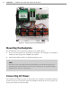
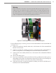
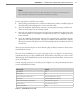
Terminating SmartSensor 6-conductor Cables
e SmartSensor Matrix will receive power once each SmartSensor 6-conductor cable is
correctly landed into the plug-in terminals on the backplate (see Figure 2.8 and Table 2.1).
Each 6-conductor cable has one DC power wire pair, two RS-485 communication pairs, and
a drain wire. e service end of the cable connects to plug-in terminals on the preassembled
backplate (see Figure 2.8).
Figure 2.8 – Color Label on Plug-in Terminals