
User guide


CHAPTER 2 CONNECTING POWER AND SURGE PROTECTION 27
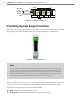
TD – Indicates when data is transmitted over the T-bus or over the control bridge. is
LED does not indicate data transmitted on the A or B ports.
RD – Indicates when data is received over the T-bus or over the control bridge. is
LED does not indicate data received on the A or B ports.
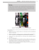
Note
If the DC Surge OK LED is not on when the Click 222 is powered, call Wavetronix Tech-
nical Services for assistance.
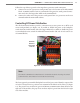
e Click 222 provides the following three independent serial connections:
Topmost jack: control bridge
Middle jack: dedicated communications for sensor 2 detection calls
Lowest jack: dedicated communications for sensor 1 detection calls
e control bridge enables a multi-drop shared communication bus between all sensors
connected to the backplate. is allows control of all SmartSensor Matrix sensors, rack
cards and other connected Click devices. e remaining two serial connection ports pro-
vide communications to only one sensor each, as outlined above.
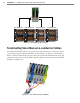
On a four-sensor preassembled backplate (see Figure 2.7):
e sensor wired into the le-most terminal blocks will be connected to ports A and
C on the Click 222 on the le. Port A is for detection calls and port C is connected to
the control bridge.
e sensor wired to the second set of terminal blocks will be wired to ports B and D
on the Click 222 on the le. Port B is for detection calls and port D is connected to the
control bridge.
e sensor wired to the third set of terminal block from the le will be wired to ports
A and C on the Click 222 on the right.
e sensor wired to the right-most terminal block will be wired to ports B and D on
the Click 222 on the right.