
User guide


CHAPTER 2 CONNECTING POWER AND SURGE PROTECTION 25
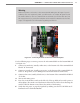
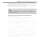
Follow the steps below to provide a low impedance protective earth connection:
1 Connect one end of a protective earth ground wire to the bottom of the PE terminal
block. A 10 AWG stranded wire is recommended for protective earth ground connec-
tions and is also the largest that will t in the terminal block.
2 Connect the other end of the protective earth ground wire to a protective earth screw
terminal within the main trac cabinet.
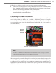
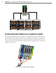
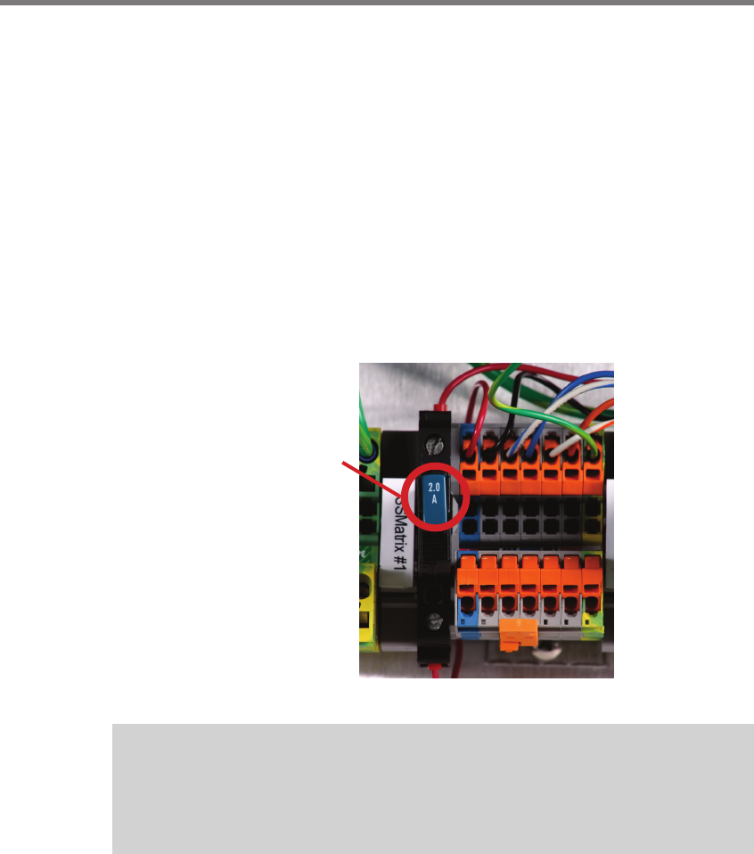
Controlling DC Power Distribution
e Click 210 circuit breakers provide a convenient way to turn power on or o for each
sensor independently (see Figure 2.4). To enable or disable DC power to the backplate,
switch the main circuit breaker (le side of upper DIN rail); to enable or disable DC power
to an individual sensor, switch the individual circuit breaker (le side of each sensor’s set
of terminal blocks).
Push this
button to
turn power
on or o
Figure 2.4 – DC Power Distribution
Note
The switch is ON when the switch button is level with the device housing; the switch
is OFF when the switch button is raised above the housing.
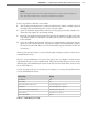
e four-approach preassembled backplate has 24 VDC power wired from the output of the
AC to DC converter into a 5-position screw terminal on the le side of the T-bus (see Figure
2.5). e green T-bus conducts DC power and RS-485 communications from the le to the
right side of the modules; the gray T-bus conducts only DC power from the le to the right
side of the modules.