
User guide


CHAPTER 1 INSTALLING THE SMARTSENSOR MATRIX 17
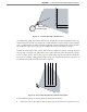
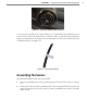
45°
45°
Edge of first lane of interest
Stop Bar
Pan sensor
towards stop bar
Figure 1.3 – Corner Radar Field of View Position
To visualize the extent of the sensor eld of view, the 90° eld of view is imprinted on the top
and bottom of the sensor case. If more of a visual indicator is needed, then a square framing
tool (e.g. raer square) or other tool with a right angle can be held above the sensor. By look-
ing down both edges of the tool, you can visualize the extent of the radar’s coverage.
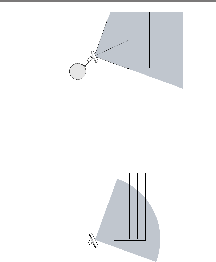
Usually the front edge of the sensor’s eld of view is aligned to provide coverage beyond
the stop bar (see Figure 1.4). is allows you to place detection zones beyond the stop bar
to detect those vehicles that do not stop at or behind the stop line and will also allow the
sensor to see vehicles exiting queues. If the sensor pole is upstream from the stop bar, it is
recommended to pan in the direction of the stop bar.
Front edge of field of view
Figure 1.4 – Sensor Aligned by Rotating Towards the Stop Bar
Use the following steps to correctly align the SmartSensor Matrix:
1 Adjust the side-to-side angle so that the front edge of the eld of view provides a view