
User guide


APPENDIX 109
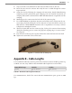
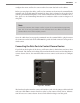
3 Insert the other end of each wire into a second 5-position connector.
4 Plug one connector into the T-bus port on the Click 600; plug the other into the end
of your T-bus.
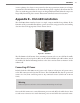
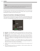
Lastly, there are four LEDs on the faceplate. ese LEDs have the following functions:
Red LED (PW) – Illuminates when device has power
Blue LED (OK) – Extinguishes if device has been disabled by surges
Green LED (TD) – Illuminates when data is transmitted on the control bus
Yellow LED (RD) – Illuminates when data is received on the control bus
Use these LEDs to monitor the state of the Click 600.
Appendix E – Matrix Extended Range
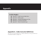
ere are a few things that you should be aware of when using SmartSensor Matrix near the
edge of its 140 foot range..
Angle Resolution
At ranges of 0–100 feet, the angular resolution is sucient to provide a ground range reso-
lution that is close to the average width of a lane. is allows the sensor algorithms to dis-
tinguish between two vehicles traveling side by side in adjacent lanes.
As the range is extended, the ground resolution gets larger. At 140 feet, the smallest beam’s
footprint is about 11 feet and the outside antennas have a footprint of about 18 feet. is
means that even though the center of the sensor’s view may be able to detect adjacent tar-
gets, these same targets may not be detected when they are close to the edges of the sensor’s
view.