
User guide


108 APPENDIX
Note
You don’t have to do anything special to tell the device to push data on any port; all
data received on any port is automatically pushed on all other ports.
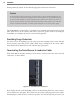
e data bus portion of the faceplate also has the following features: next to each RJ-11 jack
is a switch that turns power on and o to the associated sensor; under each jack is an LED
that illuminates when the associated sensor has power.
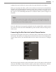
Using the Control Bus to Configure the Sensors
e lower portion of the faceplate has the ports that make up the physical interface of the
control bus. ese ports allow you to congure any sensors connected to the Click 600. You
can connect to the Click 600 and thereby to the sensors using any of the following options:
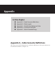
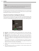
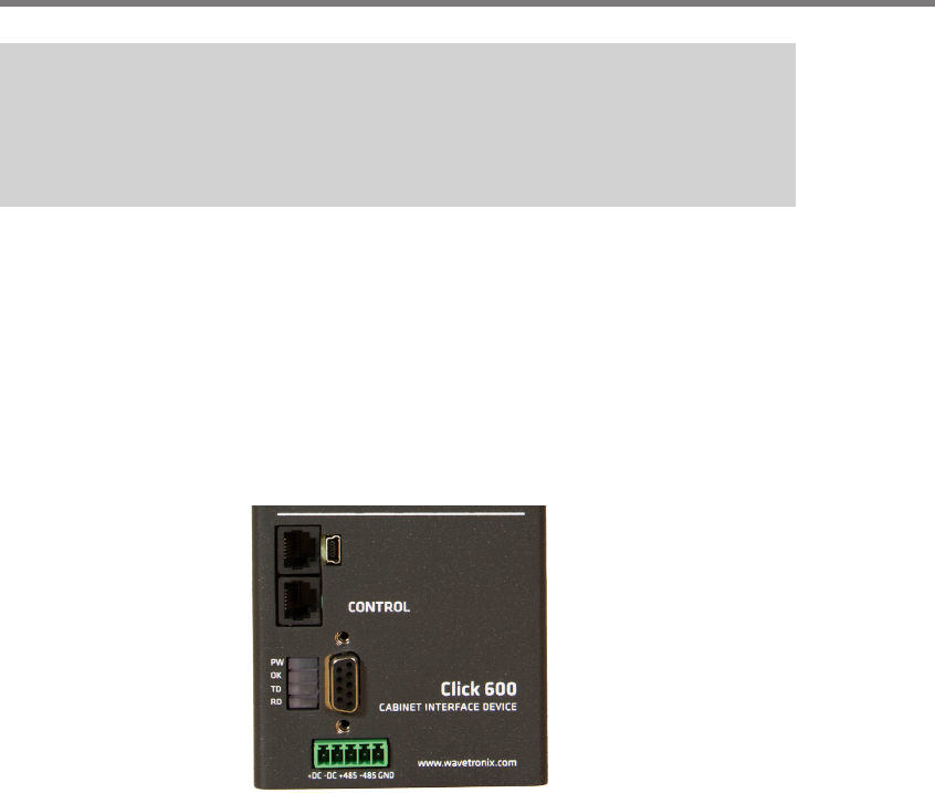
Figure D.4 – Control Bus
RJ-11 jacks – e Click 600 has two RJ-11 jacks that allow you to connect via RS-485.
USB port – Next to the RJ-11 jacks is a USB mini-B connector for connecting via USB.
DB-9 connector – Under the USB port is a DB-9 connector for connecting via RS-232.
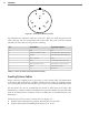
T-bus port – At the bottom of the faceplate is a T-bus connector. You can use this to
make the Click 600 part of a shared power and RS-485 communication bus. is isn’t
usually necessary because the Click 600 performs all basic necessary functions, but it
is an option.
If you do intend on doing that, see the Click 100–400 Series User Guide for informa-
tion about how to use a T-bus. Once you have your T-bus assembled and installed on a
DIN rail somewhere in the cabinet, do the following:
1 Find ve wires (or a cable) that will reach from the shelf to the T-bus; strip the ends of
each wire.
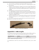
2 Insert each wire into one of the screw terminals on a T-bus 5-position connector. e
terminals are all labeled for your ease.