
User guide


APPENDIX 107
congure the sensor, and lets the sensor send its detection data back to the cabinet.
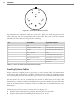
Before you can plug in the cables, you’ll need to terminate each one into the terminal blocks
included with your Click 600. e method for doing this is identical to the method used
with the preassembled backplates, so for detailed instructions on how to terminate the ca-
bles, please see the Terminating SmartSensor 6-conductor Cables section in chapter 2 of
this guide.
Note
You’ll note, however, that chapter 2 refers to part of the terminal block plug being
blue. This is the only spot where the two terminal block sets dier; the Click 600
terminal blocks won’t have any blue portions.
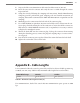
Once the cables have been properly terminated into the terminal blocks, plug them into
the connectors on the back of the Click 600. Keep track of which connector corresponds to
which sensor.
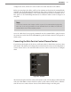
Connecting the Data Ports to Contact Closure Devices
If you look at the faceplate of the device, you’ll notice that it’s divided into two buses: Data
and Control. e data bus is for taking detection data from the sensors and sending them to
contact closure devices; the control bus allows users to connect to the sensors to congure
them.
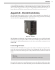
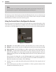
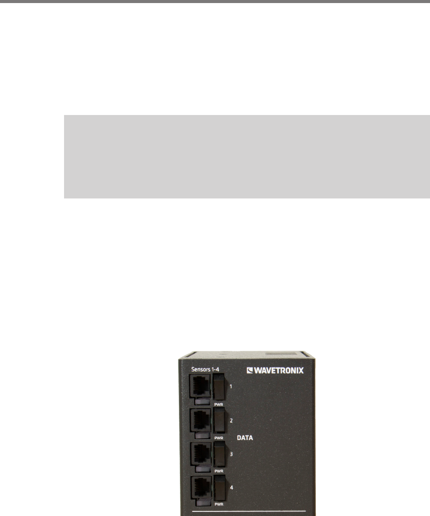
Figure D.3 – Data Bus
e data bus faceplate interface consists of four RJ-11 jacks. Use the jumper cables included
with your Click 600 to connect from these jacks to your contact closure devices. Informa-
tion on how to use contact closure devices can be found in chapter 3 of this guide.