
User guide


106 APPENDIX
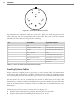
During normal operation, be sure that all appropriate switches are turned on.
Caution
An authorized electrical technician should install the preassembled backplate. Per-
sons other than authorized and approved electrical technicians should NOT attempt
to connect the backplate to a power supply and/or trac control cabinet, as there is a
serious risk of electrical shock through unsafe handling of the power source. Extreme
caution should be used when connecting the backplate to an active power supply.
e Click 600 has a connector for a 5-position screw terminal, which can be used to power
other Click devices in the cabinet; this will be covered in greater detail in the Using the
Control Bus to Congure the Sensors section of this appendix.
Providing Surge Protection
You don’t need to do anything to get the surge protection running; just be aware that this
device provides protection for the cabinet from surges coming in on the sensor cables.
(Each SmartSensor Matrix has its own onboard surge protection.)
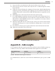
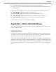
Terminating the SmartSensor 6-conductor Cable
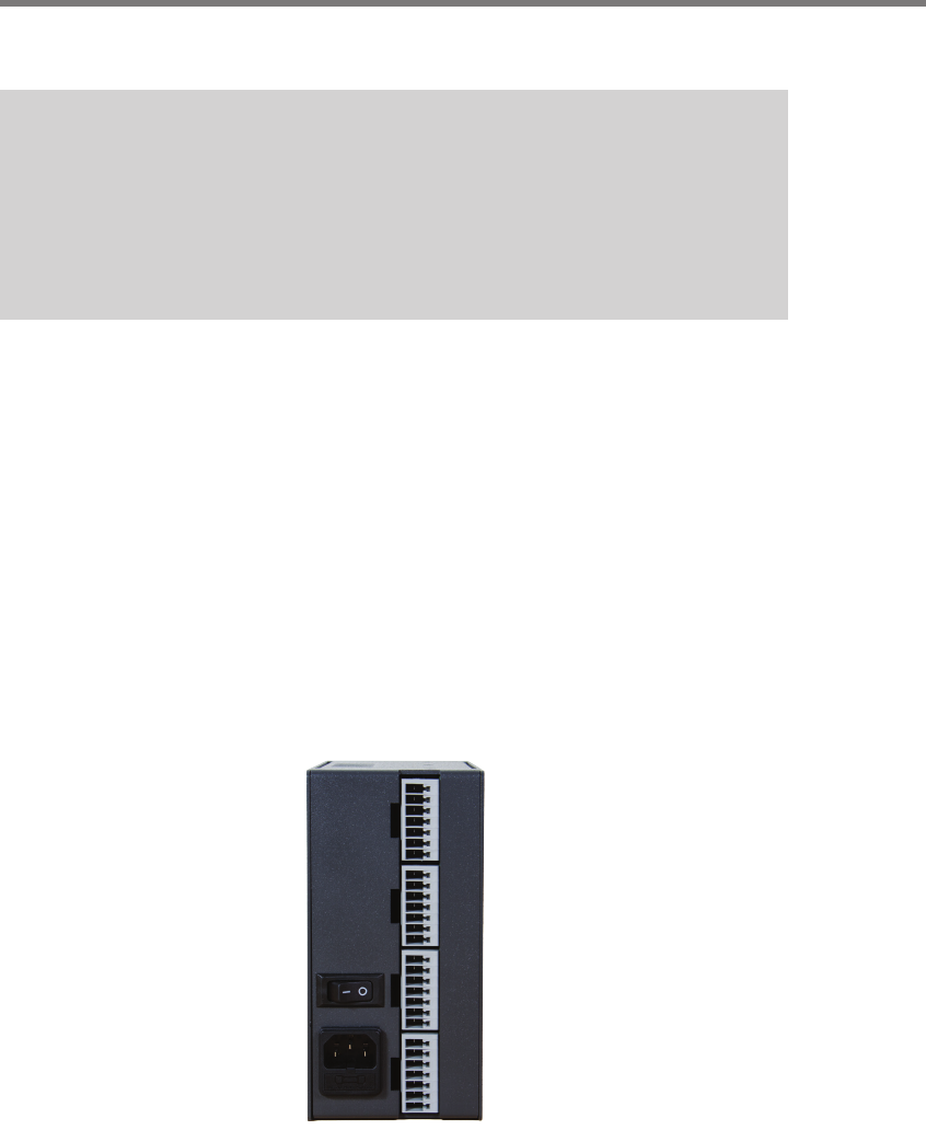
Each Click 600 can interface with up to four sensors. On the back of the device are four
connectors, as shown below.
Figure D.2 – Click 600 Sensor Connectors
If you look at the side of the Click 600, you’ll see on the label that these four sensor connec-
tors are labeled as 1 through 4. ese connectors are where you’ll plug in the sensor cables.
Terminating the cables in these connectors provides the sensors with DC power, lets you