
User guide


APPENDIX 103
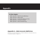
3 Strip each of the seven SmartSensor cable wires back about 1/4 in. (0.6 cm).
4 Insert the wires into the contacts and verify the wire is visible through the contact
inspection hole.
5 Crimp the wires by following the crimping tool instructions. Daniels Manufacturing
Company provides professional grade crimping tools and detailed instructions on
crimping. Wavetronix recommends the DMF AF8 M22520/1-01 or equivalent tool for
crimping.
6 Manually press the contacts into the back side of the connector plug.
7 Use a DMC DAK20 (or equivalent) insertion tool to fully seat the contact into the con-
nector plug. Check the mating face of the connector to ensure that all the contacts are
fully inserted. A DMC DRK20 extractions tool (or equivalent) is necessary to remove
a misplaced or misaligned contact.
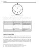
8 read the back shell onto the connector plug. To keep the connector from rotating
during the threading process, connect the plug and coupling ring to a sensor connec-
tor receptacle.
9 Press all of the connector parts together. read the strain relief onto the back shell.
10 Tighten the strain relief screws on the back.
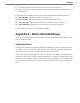
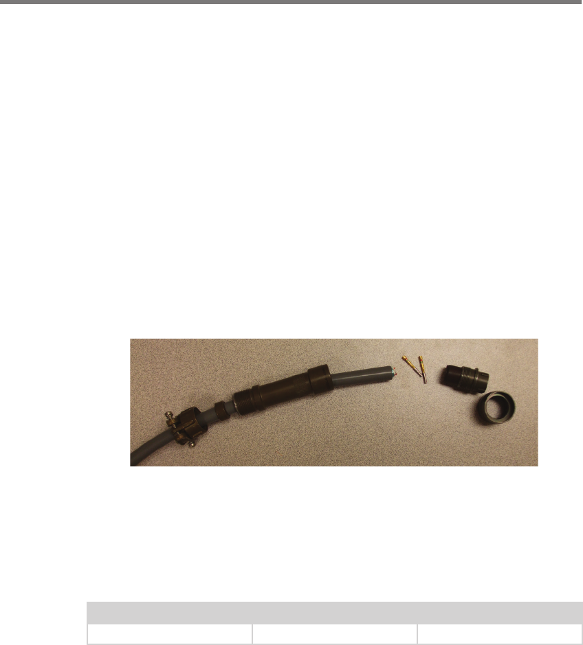
Figure A.2 – Connector Sub-assembly Parts
Appendix B – Cable Lengths
It is recommended that the sensor be powered by 24 VDC to achieve reliable operation up
to 500 . (152.4 m) away. Table B.1 lists maximum cable lengths for 12 and 24 VDC.
Power Wire Gauge 24 Volts 12 Volts
20 AWG 500 ft. (152.4 m) 90 ft. (27.4 m)
Table B.1 – Maximum Cable Length for Power (ft)
For communications, both of the sensor’s RS-485 communication ports operate at 9600
bps.