
User guide


102 APPENDIX
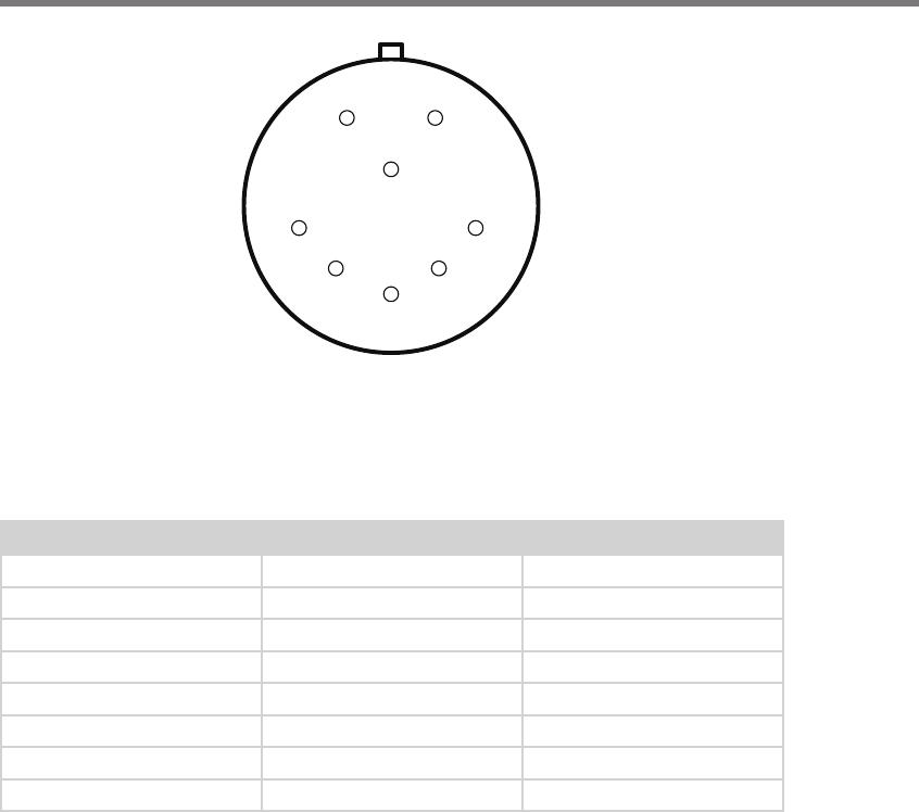
A
B
C
D
E
F
G
H
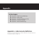
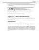
Figure A.1 – SmartSensor Matrix Connector
e SmartSensor 6-conductor cable has seven wires. Table A.1 details the pinout of the
cable connector and the corresponding wire in the cable. e sensor itself also contains
internal wires that connect to the protective earth lug.
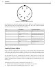
Pin Cable Wire Signal Description
A Red DC+
B Orange and white stripe Data bus 485+ (Sensor port 2)
C Orange Data bus 485- (Sensor port 2)
D Drain / Shield Drain
E Blue Control 485- (Sensor port 1)
F Blue and white stripe Control 485+ (Sensor port 1)
G Black Common (Ground)
H ---- Reserved
Table A.1 – Pinout for Power and Communication Signals
Creating Custom Cables
Proper connector crimping tools are necessary to create custom cables. e SmartSensor
6-conductor cable connector uses a MILC-C-26482 Series 1 connector, crimping contacts
and a watertight back shell. A kit with these parts can be ordered directly from Wavetronix.
Size 20 contacts are used to accommodate the 20 and 22 AWG wires in the cable. (e
SmartSensor 6-conductor cable’s red and black wires provide a 20 AWG wire pair. e other
pairs on the SmartSensor 6-conductor cable are 22 AWG and are normally used for com-
munication.)
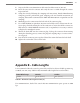
Follow the steps below to create a custom cable (see Figure A.2):
1 Slide the strain relief, follower, grommet and back shell over the cable.
2 Strip the cable jacket and shielding back about 11/2 in. (4 cm).