
User guide

INTRODUCTION SMARTSENSOR MATRIX USER GUIDE 9
signs or other at surfaces directly behind it. is will help reduce multiple reection
paths from a single vehicle.
Cable length – Make sure that you have sucient homerun and sensor cabling. Cable
runs as long as 500 . (152.4 m) can be achieved using 24 VDC operation and the sys-
tem’s native RS-485 communications. If your application requires a cable length longer
than 500 . (152.4 m), contact Wavetronix Technical Services for assistance.
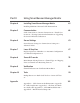
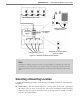
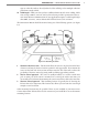
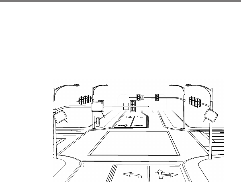
e SmartSensor Matrix should be mounted using one of the following options (see Figure
I.4):
➌
➋
➊
Figure I.4 – Mounting locations
1 The back side of mast arm – is location allows the sensor to be placed near the lanes
of interest and may be the best location option for wide approaches. If you mount the
sensor on the back side of a mast arm, mount it near the end of the arm to reduce the
possibility of the mast arm or departing trac occluding approaching vehicles.
2 The far side of approach – e sensor is usually mounted on a corner vertical mast
pole or strain pole. If the sensor is mounted on a vertical pole with a mast arm, you
can usually avoid occlusion by mounting the sensor away from or below the mast arm.
3 The near side of approach – is mounting location is typically best if detecting the
le turn lane is less important. is location also allows you to mount the sensor high
enough to avoid occlusion.
Other mounting locations may be possible if these are not available at your intersection.
Contact Wavetronix Technical Services for assistance if you would like to use an alternative
mounting location.