SmartSensor Matrix USER GUIDE
SmartSensor Matrix USER GUIDE www.wavetronix.com • 78 East 1700 South Provo, Utah 84606 • 801.734.
© 2014 Wavetronix LLC. All Rights Reserved. Wavetronix, SmartSensor, Click, Command, and all associated product names and logos are trademarks of Wavetronix LLC. All other products or brand names as they appear are trademarks or registered trademarks of their respective holders. Protected by US Patent Nos. 6,556,916; 6,693,557; 7,426,450; 7,427,930; 7,573,400; 7,889,097; 7,889,098; 7,924,170; 7,991,542; 8,248,272; 8,665,113; Canadian Patent Nos. 2461411; 2434756; 2512689; and European Patent Nos.
Contents Introduction 5 SmartSensor Matrix Package 6 • Selecting a Mounting Location 7 Part I Installing the SmartSensor Matrix Chapter 1 Installing the SmartSensor Matrix 13 Sensor Mounting Guidelines 14 • Attaching the Mount Bracket to the Pole 15 • Attaching the Sensor to the Mount Bracket 16 • Aligning the Sensor to the Roadway 16 • Applying the Silicon Dielectric Compound 18 • Connecting the SmartSensor 6-conductor Cable 18 • Grounding the Sensor 19 Chapter 2 Connecting Power and Surge Protect
Part II Using SmartSensor Manager Matrix Chapter 4 Installing SmartSensor Manager Matrix 45 Installing SSMM 46 • Microsoft .
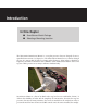
Introduction In this chapter ˽˽ SmartSensor Matrix Package ˽˽ Selecting a Mounting Location The Wavetronix SmartSensor Matrix™ is a stop bar presence detector designed for use at signalized intersections (see Figure I.1). The SmartSensor Matrix detects vehicles through the use of a 24.125 GHz (K band) operating radio frequency. Using what is classified as frequency modulated continuous wave (FMCW) radar, SmartSensor Matrix detects and reports vehicle presence in as many as 10 lanes simultaneously.
6 INTRODUCTION • SMARTSENSOR MATRIX USER GUIDE ration process is quick and easy. After installation, the sensor will require little or no on-site maintenance and can be remotely configured. This user guide outlines the step-by-step process of installing and configuring the SmartSensor Matrix. Any questions about the information in this guide should be directed to Wavetronix or your distributor.
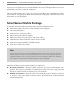
INTRODUCTION • SMARTSENSOR MATRIX USER GUIDE Control Bridge to Rack Cards AC Power Conversion Option Control Bridge on T-bus Configuration Toolkit (attach to T-bus) Remote IP Connection Option (attach to T-bus) Figure I.2 – SmartSensor Matrix System Options Control Bridge to Sensors Note SmartSensor Matrix systems provide a control bridge to manage all connected SmartSensor and Click devices.
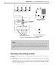
INTRODUCTION • SMARTSENSOR MATRIX USER GUIDE 140 ft 8 Sensor Pole 140 ft Figure I.3 – Corner Radar ˽˽ Line of sight – Position the sensor so that it will be able to detect the entire area of interest. Avoid occlusion by installing the sensor away from trees, signs and other roadside structures. ˽˽ Detection coverage – Position the sensor so that it will be able to reach all the specified stop bar detection zones.
INTRODUCTION • SMARTSENSOR MATRIX USER GUIDE signs or other flat surfaces directly behind it. This will help reduce multiple reflection paths from a single vehicle. ˽˽ Cable length – Make sure that you have sufficient homerun and sensor cabling. Cable runs as long as 500 ft. (152.4 m) can be achieved using 24 VDC operation and the system’s native RS-485 communications. If your application requires a cable length longer than 500 ft. (152.4 m), contact Wavetronix Technical Services for assistance.
Part I Installing the SmartSensor Matrix Chapter 1 – Installing the SmartSensor Matrix Chapter 2 – Connecting Power and Surge Protection Chapter 3 – Contact Closure Communication
Installing the SmartSensor Matrix 1 In this chapter ˽˽ ˽˽ ˽˽ ˽˽ ˽˽ ˽˽ ˽˽ Sensor Mounting Guidelines Attaching the Mount Bracket to the Pole Attaching the Sensor to the Mount Bracket Aligning the Sensor to the Roadway Applying the Silicon Dielectric Compound Connecting the SmartSensor 6-conductor Cable Grounding the Sensor 1 The installation process includes attaching the mounting bracket to the pole; attaching the sensor to the mounting bracket; aligning the sensor; applying a silicon dielectric compou
14 CHAPTER 1 • INSTALLING THE SMARTSENSOR MATRIX Warning Use caution when installing any sensor on or around active roadways. Serious injury can result when installation is performed using methods that are not in accordance with authorized local safety policy and procedures. Always maintain an appropriate awareness of the traffic conditions and safety procedures as they relate to specific locations and installations.
CHAPTER 1 • INSTALLING THE SMARTSENSOR MATRIX ˽˽ Take into consideration the sensor’s field of view, which reaches 140 ft. (42.7 m) from the sensor. Place the sensor so that the field of view covers all the areas of interest. ˽˽ The mast arm is frequently a good place to mount the sensor. ˽˽ The mounting position should have a clear view of the detection area. Poles, mast arms, signal heads, or other objects should not block the view of the detection area.
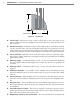
16 CHAPTER 1 • INSTALLING THE SMARTSENSOR MATRIX One swivel joint is used to pan the sensor field of view left or right and the other swivel joint is used to tilt the sensor down towards the roadway. If you are not using the double swivelmount, make sure the pole straps are adjustable at this point in the installation process.
Edge of first lane of interest CHAPTER 1 • INSTALLING THE SMARTSENSOR MATRIX 45° 45° Pan sensor towards stop bar Stop Bar Figure 1.3 – Corner Radar Field of View Position To visualize the extent of the sensor field of view, the 90° field of view is imprinted on the top and bottom of the sensor case. If more of a visual indicator is needed, then a square framing tool (e.g. rafter square) or other tool with a right angle can be held above the sensor.
18 CHAPTER 1 • INSTALLING THE SMARTSENSOR MATRIX 2 3 downstream of the stop bar. Tilt the sensor down so it is aimed at the center of the lanes of interest. If necessary, rotate the sensor so that the bottom edge of the sensor is parallel with the roadway. This is necessary where the intersection approach has a significant grade.
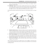
CHAPTER 1 • INSTALLING THE SMARTSENSOR MATRIX Figure 1.6 – Sensor 6-conductor Cable Connector To set up your network in an orderly fashion, it is recommended that labeling be used on the service end of each SmartSensor 6-conductor cable. A convenient way to label the cables is to mark the last seven digits of the serial number on each sensor and the direction of traffic monitored (see Figure 1.7). Figure 1.
20 CHAPTER 1 • INSTALLING THE SMARTSENSOR MATRIX Caution Be careful of Electrostatic Discharge (ESD) when handling the SmartSensor Matrix device before and during installation. ESD triggered by the sensor handler, particularly on the outer grounding lug before being properly grounded, may cause harmful effects to internal Matrix components.
Connecting Power and Surge Protection 2 In this chapter ˽˽ ˽˽ ˽˽ ˽˽ Mounting the Backplate Connecting AC Power Providing System Surge Protection Terminating SmartSensor 6-conductor Cables 2 After installation, each SmartSensor Matrix will need to be integrated into the main traffic cabinet for power and surge protection.
22 CHAPTER 2 • CONNECTING POWER AND SURGE PROTECTION Figure 2.1 – Intersection Preassembled Backplate Mounting the Backplate Use the following steps to mount the backplate in the traffic cabinet: 1 2 Locate the area planned for mounting the backplate. The backplate can usually be mounted on the side panel of a NEMA-style cabinet. Attach the backplate with the U-channel mounting screws.
CHAPTER 2 • CONNECTING POWER AND SURGE PROTECTION Warning Make sure power to AC mains is disconnected while wiring the AC input. If your installation does not require AC power, you will need to use surplus DC power inside the traffic cabinet. In this case, Wavetronix recommends you use the Click 221 (8 A DC surge protector) to protect the backplate and SmartSensor Matrix units from DC surges. See Appendix C for information regarding the Click 221. Figure 2.
24 CHAPTER 2 • CONNECTING POWER AND SURGE PROTECTION Caution An authorized electrical technician should install the preassembled backplate. Persons other than authorized and approved electrical technicians should NOT attempt to connect the backplate to a power supply and/or traffic control cabinet, as there is a serious risk of electrical shock through unsafe handling of the power source. Extreme caution should be used when connecting the backplate to an active power supply.
CHAPTER 2 • CONNECTING POWER AND SURGE PROTECTION Follow the steps below to provide a low impedance protective earth connection: 1 2 Connect one end of a protective earth ground wire to the bottom of the PE terminal block. A 10 AWG stranded wire is recommended for protective earth ground connections and is also the largest that will fit in the terminal block. Connect the other end of the protective earth ground wire to a protective earth screw terminal within the main traffic cabinet.
26 CHAPTER 2 • CONNECTING POWER AND SURGE PROTECTION +24V DC -DC +RS-485 -RS-485 GND Power (red wire ) ( black wire ) Green Gray Green RS-485 Figure 2.5 – T-bus Pinout Diagram Providing System Surge Protection The Click 222 system surge protector is designed to prevent electrical surges conducted along underground cables from damaging the cabinet equipment (see Figure 2.6). Figure 2.
CHAPTER 2 • CONNECTING POWER AND SURGE PROTECTION ˽˽ TD – Indicates when data is transmitted over the T-bus or over the control bridge. This LED does not indicate data transmitted on the A or B ports. ˽˽ RD – Indicates when data is received over the T-bus or over the control bridge. This LED does not indicate data received on the A or B ports. Note If the DC Surge OK LED is not on when the Click 222 is powered, call Wavetronix Technical Services for assistance.
28 CHAPTER 2 • CONNECTING POWER AND SURGE PROTECTION Port A & Port C x OUT x x x x x x x x x x x x x x x x PWR GND 485+ 485- 485+ 485- DRN IN x x x x x x x x x x OUT x x x x x x IN x x x x x x x x x PWR GND 485+ 485- 485+ 485- DRN x Port B & Port D OUT x x x x x x x PWR GND 485+ 485- 485+ 485- DRN SSMatrix #4 x x Port A & Port C SSMatrix #3 x OUT SSMatrix #2 x x x PWR GND 485+ 485- 485+ 485- DRN IN Port B & Port D IN x x x x x x
CHAPTER 2 • CONNECTING POWER AND SURGE PROTECTION Note Do not strip the service end of the cable until after it has been routed through conduit. The cable should be one continuous run without any splices. Use the steps below to land the sensor cables: 1 2 3 4 After routing your SmartSensor 6-conductor cable into the cabinet, carefully strip back the cable jacket and shielding on the service end of the cable.
Contact Closure Communication 3 In this chapter ˽˽ ˽˽ ˽˽ ˽˽ ˽˽ Using the Click 112/114 DIP Switches Using the Click 104 Rotary Switch Attaching and Programming the Click 112/114 Attaching and Programming the Click 104 Channel Mapping 3 Each SmartSensor Matrix communicates with standard traffic cabinets using either the Click 104 DIN rail contact closure module or the Click 112/114 detector rack cards (see Figure 3.1).
32 CHAPTER 3 • CONTACT CLOSURE COMMUNICATION Note See the Click 100–400 Series User Guide for complete information on how to connect and configure the Click 104 DIN rail contact closure module and the Click 112/114 detector rack cards. Each SmartSensor Matrix could potentially use up to 16 channels using a combination of Click 104/112/114 contact closure modules. This means that a standard four-approach stop bar detection system can be accommodated by a 64-channel detector rack.
CHAPTER 3 • CONTACT CLOSURE COMMUNICATION Note An advantage of using the DIP switches for configuration is that if you ever need to replace a Click 112/114, you can simply set the DIP switches on the new card to match the pattern of the DIP switches on the card you are replacing, then slide the new one into the same slot in the detector rack. Click 114 Input Mapping DIP Switch Settings On a Click 114, channel group 1 comprises input channels 1–4.
34 CHAPTER 3 • CONTACT CLOSURE COMMUNICATION Input Mapping Switches Baud Rate Switches S4 S5 4 1 2 3 3 5 6 7 8 Channel Group 1 2 On 6 4 Bus 1 5 7 8 Off Bus 2 Click 112 –Selects channels 1 & 2 Figure 3.4 – Click 112 DIP Switches for Channels 1 and 2 Figure 3.5 shows how to set the DIP switches on the Click 112 on the right. This will assign sensor output channels 3 and 4 for output.
CHAPTER 3 • CONTACT CLOSURE COMMUNICATION As shown in the table below, the outputs are mapped sequentially—that is, they can only be mapped in numerically ordered groups of four (1–4, 5–8, etc.). If you set the switch to 3, for 9–12, then sensor channel 9 would be mapped to output 1, sensor channel 10 would be mapped to output 2, sensor channel 11 would be mapped to output 3, and sensor channel 12 would be mapped to output 4.
36 CHAPTER 3 • CONTACT CLOSURE COMMUNICATION 4 5 6 7 Connect a 6-ft. (1.8-m) patch cord from the Click 222 RS-485 B port to a bus 1 port on another rack card. If you are using Click 112 cards, use an 6-in. (15-cm) patch cord to share bus 1 between cards dedicated to the same sensor. Also, configure one card to use Matrix channels 1 and 2 and configure the other card to use Matrix channels 3 and 4.
CHAPTER 3 • CONTACT CLOSURE COMMUNICATION Detection Channel Menu Level 2 Menu Level 1 Mode Switch Figure 3.7 – Click 112/114 Menu Normally, a SmartSensor Matrix sensor will send 10 contact closure messages each second. If a rack card does not receive communications from a sensor within 10 seconds, the rack card will go into fail-safe mode and all of the contact closures will be activated and the corresponding detection channel LEDs on the faceplate will turn on.
38 CHAPTER 3 • CONTACT CLOSURE COMMUNICATION 3 If needed, daisy-chain multiple Click 104 devices together by utilizing both RJ-11 jacks on each device’s faceplate. Click 104 LEDs The front panel of the device features a push-button and three banks of LEDs for on-device configuration and monitoring. The first bank of LEDs, labeled Channel, displays the state of the contact closure outputs (see Figure 3.9). 1 Channel 2 3 Menu 4 PWR OK TD RD Figure 3.
CHAPTER 3 • CONTACT CLOSURE COMMUNICATION 4 5 6 menu option. Press and hold the mode switch to cycle through the submenu. The Level 2 LEDs will light to indicate that the device is cycling though all configuration options. Release the mode switch once the desired configuration option is reached. Quickly press and release the mode switch to select the current configuration option.
40 CHAPTER 3 • CONTACT CLOSURE COMMUNICATION NEMA TS2, 2070 and other advanced traffic cabinet systems usually allow software programming of the detector card channel outputs to traffic phases via a channel-to-phase mapping grid in the controller menu. Figure 3.12 illustrates how the detector channels 1 to 16 of a NEMA TS-2 rack can be assigned to the standard eight phases using four Click 114 cards.
Part II Using SmartSensor Manager Matrix Chapter 4 – Installing SmartSensor Manager Matrix Chapter 5 – Communication Chapter 6 – Sensor Settings Chapter 7 – Lanes & Stop Bars Chapter 8 – Zones & Channels Chapter 9 – Verification Chapter 10 – Tools
Installing SmartSensor Manager Matrix 4 In this chapter ˽˽ Installing SSMM ˽˽ Microsoft .NET Framework 4 The SmartSensor Manager Matrix (SSMM) software enables you to configure and interact with the SmartSensor Matrix. SSMM can be run on any Windows-capable device up to and including Windows 8. Note Windows RT, found on many new Windows tablets, is distinct from Windows 8 and will not run SmartSensor Manager Matrix. The software can be downloaded on other computers by going to www.wavetronix.com.
46 CHAPTER 4 • INSTALLING SMARTSENSOR MANAGER MATRIX wireless link. Follow the steps below to use the Click 421 to communicate with the SmartSensor Matrix: 1 2 Rock the Click 421 device onto the green T-bus to the left of the gray T-bus connector on the second DIN rail on the backplate. Make a wired (using the serial port on the front of the device) or wireless (Bluetooth) connection between the Click 421 and the handheld computer.
CHAPTER 4 • INSTALLING SMARTSENSOR MANAGER MATRIX Figure 4.1 – SSMM Setup Wizard 4 Select an installation location. The default location provided is normally “C:\Program Files\Wavetronix.” If desired, click Browse to choose another location (see Figure 4.2). Figure 4.2 – Location to be Installed 5 6 Click the Install Now button. After SSMM is installed, you can create shortcuts to the SSMM software on the desktop and in the Start menu using the corresponding checkboxes (see Figure 4.3).
48 CHAPTER 4 • INSTALLING SMARTSENSOR MANAGER MATRIX 8 SSMM software. A PDF reader program (i.e. Adobe Acrobat Reader) is required to view the release notes. Click Finish to complete the setup process. Note SSMM is designed for the 96 DPI display setting. The application may not display text properly, and may not function properly in general, if the display is not set to 96 DPI. Microsoft .NET Framework The SSMM setup program will automatically detect whether Microsoft .NET Framework v3.
Communication 5 In this chapter ˽˽ ˽˽ ˽˽ ˽˽ ˽˽ Serial Connection Internet Connection Virtual Connection Viewing Connection Info Upgrading the Sensor’s Embedded Software 5 Once the sensors are installed, use the SSMM software to change settings, view data and configure the sensors to the roadway. Launch SSMM by either clicking on the icon that was placed on your desktop or clicking the icon found in the Start menu. The SSMM splash screen and then main screen shown in Figure 5.1 will appear.
50 CHAPTER 5 • COMMUNICATION Figure 5.1 – SSMM Splash Screen (left) and Main Screen (right) You can always view the version of SSMM you are using by right-clicking on the main screen and then clicking SSM Matrix Version. To see the version, date and timestamp of the individual components that make up the program, select Component Version (see Figure 5.2). Figure 5.
CHAPTER 5 • COMMUNICATION The first step is to make a connection to the sensor. The following three types of connections can be made: ˽˽ Serial connection – Connect using Bluetooth, RS-232, or RS-485 communication. ˽˽ Internet connection – Connect using an IP address and a serial to Ethernet converter. ˽˽ Virtual connection – Connect to a virtual sensor within software (used for learning and demonstrating SSMM functionality).
52 CHAPTER 5 • COMMUNICATION Figure 5.3 – Serial Connection After you have connected to a sensor, the next time you would like to connect you can simply click the magnifying glass icon in the upper right corner of the screen. This will take you to the last connection settings you used to connect to a sensor. The first time you connect to a sensor, the default Sensor ID will be the last seven digits of the sensor’s serial number.
CHAPTER 5 • COMMUNICATION Figure 5.4 – Sensor Info Screen The Sensor Info screen lists the following sensor settings and version information: ˽˽ Sensor ID – The last seven digits of the sensor serial number. This field is not editable. ˽˽ Description – Used to describe the application (e.g. stop bar detection); can also be used for GPS coordinates. This field is not editable from this screen. ˽˽ Location – Used to describe the intersection where the sensor is located.
54 CHAPTER 5 • COMMUNICATION 420 serial to 802.11b converter. The Click 420 provides serial devices with an IP address on a wireless 802.11b network. ˽˽ Internet Service Providers – The SmartSensor Matrix can be equipped with optional external modems (CDMA, GMS or GPRS) and assigned an Internet address on these networks. (Please contact Wavetronix Technical Services for assistance.) Note The Internet connection is made to the control bridge and NOT to the data ports.
CHAPTER 5 • COMMUNICATION Figure 5.6 – Internet Connection Screen 9 Click the Connect button. When a connection is established you will be directed back to the home page. If you have problems connecting: 1 2 Make sure that all power and communication wiring is correct. Check the address and port number. Connection failure can occur for various reasons; if a failure occurs repeatedly, call Wavetronix Technical Support for assistance.
56 CHAPTER 5 • COMMUNICATION Deletes an Address Book Imports an Address Book Exports an Address Book Edits the Selected Device Adds a Device to the Address Book Deletes a Device from the Address Book Figure 5.7 – Address Book Virtual Connection A virtual connection allows you to use the SSMM software without being connected to an actual sensor.
CHAPTER 5 • COMMUNICATION Figure 5.8 – Virtual Connection Screen 3 4 5 6 Select or create a virtual sensor file (.vsf) by clicking the magnifying glass icon. Click the Search button. This may take up to 30 seconds while the sensors on your virtual control bus are discovered and listed. (You can click Cancel if the sensor of interest has already been listed.) Click on the desired row from the list to select a sensor. Click the Connect button.
58 CHAPTER 5 • COMMUNICATION Note To configure channels for a future installation, connect using a virtual connection, create a virtual sensor file and then back up the configuration settings that you created. After the file is successfully backed up, the virtual sensor file will change to a sensor setup file and can be restored to any sensor in the field. When a connection is made to the SmartSensor Matrix, the main menu will appear and all configuration options will become available (see Figure 5.9).
CHAPTER 5 • COMMUNICATION Below is a list of the information available on the Connection Info screen: ˽˽ ˽˽ ˽˽ ˽˽ ˽˽ Status – Shows that you are connected. Sensor – Shows the subnet and sensor ID. Type – Shows the type of connection. Duration – Shows how long you have been connected. Failures – Shows the amount of failures during the connection, the percentage rate of failure and a link to the communication error log.
60 CHAPTER 5 • COMMUNICATION sion Control screen may appear asking you to install firmware upgrades (see Figure 5.13). If you think you have reached this screen in error, clicking the Recheck button will have the software retry and ensure that there has not been a communication issue. Clicking the Details button will display the current sensor and software information. Click the UPLOAD FIRMWARE button to upgrade the software.
CHAPTER 5 • COMMUNICATION SSMM firmware version date is more recent than the sensor firmware version date, the newer firmware will need to be installed; if the sensor’s firmware date is more recent than the SSMM firmware version date, a warning will appear notifying you that older firmware will be uploaded to the sensor (see Figure 5.13). Figure 5.
Sensor Settings 6 In this chapter ˽˽ General Sensor Settings ˽˽ Comm Sensor Settings ˽˽ Advanced Sensor Settings 6 Click the Sensor Settings link on the main menu to change and save settings on the sensor. General Sensor Settings The General tab of the Sensor Settings screen allows you to change the sensor description, RF channel and other settings (see Figure 6.1).
64 CHAPTER 6 • SENSOR SETTINGS Figure 6.1 – Serial Settings Window The General tab contains the following fields: ˽˽ Serial Number – Contains the sensor serial number and cannot be edited. ˽˽ Sensor ID – Contains the ID used to uniquely identify all sensors on a multi-drop bus. This ID is the last seven digits of the sensor’s serial number and cannot be edited. ˽˽ Description – Allows you to enter a description for each sensor. Limited to 64 characters.
CHAPTER 6 • SENSOR SETTINGS Figure 6.2 – Comm Tab ˽˽ Response Delay – Used to configure how long the sensor will wait before responding to a message received. This is useful for some communications devices that are unable to quickly change transmission direction. The default value is 10 milliseconds. This value can be selected for both of the sensor’s ports independently. Note In many cases, SSMM will be connected over port 1.
66 CHAPTER 6 • SENSOR SETTINGS ˽˽ Source – In normal use, the source is always the radar antenna. However, in some cases, other sources may be used for demonstrations or evaluations. When the source is switched to Diagnostic, the antenna is no longer used. Instead, a predetermined sequence of traffic will appear. Advanced Tab The Advanced tab contains higher-level features that will not typically need to be adjusted by normal users (see Figure 6.3). Figure 6.
Lanes & Stop Bars 7 In this chapter ˽˽ ˽˽ ˽˽ ˽˽ Display Options Menu Bar Automatic Configuration Manual Configuration 7 After Sensor Settings, the next option available from the main menu is Sensor Setup. When you click this option, the first screen that appears is Lanes & Stop Bars. The Lanes & Stop Bars screen shows the sensor’s 140-ft. (42.7-m), 90° degree view and provides automatic and manual controls to quickly and easily configure the sensor to the roadway.
68 CHAPTER 7 • LANES & STOP BARS Vehicle detections are represented by tracks (a series of dots) along the sensor’s view. The vehicle tracks show where the sensor is detecting traffic and will later help you configure lanes. Vehicle track history can be cleared from the screen by clicking the Clear Tracks button below the sensor view. Note Vehicle tracks are not constrained to lanes, even after you have saved a lane configuration to the sensor.
CHAPTER 7 • LANES & STOP BARS The Edit Area also contains the approach name in a small window outside of the sensor’s view (see Figure 7.3) If needed, click on the name box to see the entire approach name. This allows you to always know which approach is being configured. The approach name can be edited in the Sensor Settings window. Figure 7.3 – Approach Name Saved Configuration Overlay The Saved Configuration overlay shows everything that has been saved to the sensor (see Figure 7.4).
70 CHAPTER 7 • LANES & STOP BARS Figure 7.5 – Automatic Configuration Overlay SmartSensor Matrix is constantly running the auto-configuration process in order to find undiscovered lanes and stop bars. During this process, lanes will appear in the Auto Cfg overlay. You will need to select and capture auto-configured lanes in order to save them to the sensor (see the Capturing Lanes and Stop Bars section below). Wait at least 2–3 cycles of the intersection to accurately detect the lanes and stop bars.
CHAPTER 7 • LANES & STOP BARS Figure 7.6 – Capture Window Note If a stop bar is found for a lane during the auto-configuration process, it will be captured with the lane. Menu Bar The menu bar at the bottom of the screen allows you to perform a variety of operations during sensor configuration. Click the button at the right side of the menu bar to open a window that shows descriptions for the various menu icons (see Figure 7.7). Figure 7.
72 CHAPTER 7 • LANES & STOP BARS Saving the Configuration After automatic and manual configuration is complete, click the Save Config button to save the changes to the sensor. If you attempt to leave the Lanes & Stop Bar view before saving your changes, the following prompt will appear (see Figure 7.8). Figure 7.8 – Save Changes Dialog Moving the Sensor View The SSMM software shows the position of the SmartSensor Matrix and the view is drawn from the perspective of the sensor.
CHAPTER 7 • LANES & STOP BARS Figure 7.9 – Restart or Reboot Window Note After you have mounted and aligned the sensor, you should always reboot the sensor so that thresholds can adjust to the current view. Editing Thresholds Warning Changing Matrix thresholds can have an adverse effect on Matrix performance when done incorrectly. It is recommended only to edit the Matrix thresholds under the direction of Wavetronix Technical Support. 1 2 Click on the Edit Thresholds button.
74 CHAPTER 7 • LANES & STOP BARS Figure 7.11 – Zoom In Feature After you click on Adjust Bins or Adjust All, the Sensitivity Slider window will appear (see Figure 7.12). Click on the up/down buttons to change the sensitivity (in decibels). Negative values will lower the rejection threshold in order to increase sensitivity; positive values will increase the rejection threshold in order to decrease sensitivity. Figure 7.
CHAPTER 7 • LANES & STOP BARS Manual Configuration After the automatic configuration process is complete, manual adjustments can be made to fine-tune the sensor configuration. In some cases, it will be easier to configure the sensor manually than to use the auto-configured lanes and stop bars.
76 CHAPTER 7 • LANES & STOP BARS Figure 7.15 – Moving Lane Outside Edit Area Inserting/Deleting/Moving a Stop Bar To insert a lane stop bar: 1 2 3 Select a lane in the edit area. Click on the selected lane again to bring up the Edit Lane window (see Figure 7.14). Click on the Insert Stop Bar option of the Edit Lane window. To delete a lane stop bar: 1 2 Select a lane in the edit area. Click on the Delete Stop Bar option of the Delete Stop Bar window (see Figure 7.16). Figure 7.
CHAPTER 7 • LANES & STOP BARS To delete a lane node: 1 2 3 Select a lane in the edit area. Click on the selected lane in the vicinity of the desired node to bring up the Node Adjustment window (see Figure 7.17). Click on the Delete Node option. Figure 7.17 – Node Adjustment Window Moving a Lane Node 1 2 Select a lane in the edit area. Click and drag the lane node to the desired location (see Figure 7.18).
78 CHAPTER 7 • LANES & STOP BARS Adjusting the Width of a Lane Node Adjusting the width of a lane node will adjust the width of the lane. 1 2 3 Select a lane in the edit area. Click on the selected lane and then click again on the node that will be adjusted and the Edit Node window will appear. Change the width (in feet) of the node, by clicking the Width up/down buttons or enter the desired node width in the Width field. Adjusting the node width will impact detection search area for that lane.
Zones & Channels 8 In this chapter ˽˽ Menu Bar ˽˽ Placing Zones ˽˽ Measuring Zones 8 After you have configured the lanes and stop bars, click on tab 2 to configure the zones and channels. The Zones & Channels screen allows you to place zones and configure detection channels (see Figure 8.1). Figure 8.1 – Zones & Channels Tab Each Matrix sensor supports up to 16 zones and 16 channels. If unused, the 16 zones are stacked outside the sensor view and labeled Z1–Z16.
80 CHAPTER 8 • ZONES & CHANNELS When you enter the Zones & Channels tab and you haven’t yet configured any zones, you will be prompted to add auto zones (see Figure 8.2). If you click Yes, a zone will be placed in each configured lane. Lanes and stop bars must be defined before you can add auto zones. Note Lanes and stop bars must be defined and saved before you will be able to add auto zones. Figure 8.
CHAPTER 8 • ZONES & CHANNELS Figure 8.3 – Zones & Channels Menu Bar The Zones & Channels menu bar contains the following options: ˽˽ ˽˽ ˽˽ ˽˽ ˽˽ ˽˽ ˽˽ ˽˽ To Main Menu – Returns you to the main menu. Save Config – Saves the zones and channel mapping to the sensor. Undo Changes – Undoes changes made to the zones and channels. Edit Zone – Allows you to move a zone and specify the channels to which it is mapped. Zone/Channel Map – Allows you to map zones to channels.
82 CHAPTER 8 • ZONES & CHANNELS Editing Zones Click the Edit Zone button to adjust the currently selected zone. An entire zone can be moved by clicking and dragging or by using the arrow buttons on the Edit Zone window (see Figure 8.5). Zones can overlap each other. This window can also be used to add a delay or extend time (in seconds) to this particular zone. Figure 8.
CHAPTER 8 • ZONES & CHANNELS Normal Channel The normal channel detects presence in the zone. This means that as soon as the leading edge of the vehicle breaks the plane of the leading edge of the zone, the channel will be activated (see Figure 8.7). Pulse Channel LED Channel LED Channel LED Figure 8.7 – Normal Channel If there are no delay or extend settings, the zone will remain activated until all cars have exited the zone.
84 CHAPTER 8 • ZONES & CHANNELS Pulse Channel A pulse activates the channel for a very short period of time once the front edge of the vehicle crosses the leading edge of the zone (see Figure 8.9). You can configure how long you would like the pulse to be by changing the pulse channel width setting (see Figure 8.13). A new pulse will only be sent after a car enters a zone when the zone is empty. Pulse Channel LED Channel LED Channel LED Figure 8.
CHAPTER 8 • ZONES & CHANNELS Figure 8.10 – Zone/Channel Map Window Each channel column contains channel number and channel type (N=normal, C=count, P=pulse). Click on the individual zones in the zone column to highlight the zones in the edit area. Editing Channels The Edit Channel button will allow you to choose the channel type, map/un-map zones to a selected channel, and change delay/extend settings (see Figure 8.11).
86 CHAPTER 8 • ZONES & CHANNELS Figure 8.12 – Output Settings (Normal, Counting, Pulse) ˽˽ Detector Input – The Detector Input number provides a way for you to map inputs to the intersection phase in the controller. By default, the Detector Input will be set to “00;” if the input is left at “00,” then it is unassigned. This setting is for reference purposes only and does not actually change the sensor.
CHAPTER 8 • ZONES & CHANNELS Figure 8.13 – Output Settings Pop-up The dashes in the table mean that those particular settings are disabled due to the selected channel type. Double click on any channel row to change the output settings for that channel. Measuring Zones The SSMM software contains a feature that allows you to see how large a zone is as well as a number of other distance measurements.
88 CHAPTER 8 • ZONES & CHANNELS where on the edit area and used to measure anything in the sensor’s view (see Figure 8.15). These flags will NOT be saved to the sensor. Figure 8.
9 Verification In this chapter ˽˽ Channel Indicators ˽˽ Verification Menu Bar 9 After the configuration is complete, you will need to verify that the sensor was configured correctly. To verify lane configuration and channel mapping, click on tab 3. This will bring up the Verification window (see Figure 9.1). Figure 9.1 – Verification View In the Verification window, vehicle detections will appear as light blue rectangles.
90 CHAPTER 9 • VERIFICATION Vehicle detections in a stopped queue are represented by a stationary light blue rectangle. Channel Indicators When detections enter a zone, they will cause the indicators for the channel mapped to that zone to turn red. To see the zones mapped to a particular channel, select that channel by clicking on its indicator (see Figure 9.2). Active zones for the selected channel will be red; inactive zones for the selected channel will be gray.
CHAPTER 9 • VERIFICATION Figure 9.3 – Delay and Extend Zone Settings When vehicles stop before and after a zone, the stopped vehicle queue is extended to fill the space between the two vehicles. This ensures that a queue of vehicles that extends in front and behind a zone will always activate the zone even if the vehicles are not directly over it (see Figure 9.4). Stopped Vehicle Stopped Vehicle Queue Extension Stopped Vehicle Figure 9.
92 CHAPTER 9 • VERIFICATION undo your last edit, edit thresholds and pause/play traffic (see Figure 9.6). Click the ton at the right side of the menu bar to see a window with menu descriptions. but- Figure 9.6 – Verification View Menu Bar The Verification menu bar contains the following options: ˽˽ To Main Menu – Returns you to the main menu. ˽˽ Save Config – Saves the zones and channel mapping to the sensor.
10 Tools In this chapter ˽˽ ˽˽ ˽˽ ˽˽ Backup/Restore Rack Cards Tools Tracker Logging Sensor Self Tests 10 The Tools screen allows you to back up or restore your sensor configuration, log vehicle detections, and perform several other functions (see Figure 10.1). When connected to a sensor, all the options will be active except for the Rack Card Tools option. When a sensor connection is not active, the Rack Card Tools option will be available but the other options will not. Figure 10.
94 CHAPTER 10 • TOOLS Backup/Restore To back up or restore the sensor settings that you have changed, click the Backup/Restore button on the Tools screen (see Figure 10.2). Figure 10.2 – Backup/Restore To create a backup, click on the magnifying glass icon in the Back-up File section. Choose a destination, type in a filename for your new backup and click OK, then click the Back-up Sensor Setup button. Note The backup will appear as an .mxc file.
CHAPTER 10 • TOOLS Rack Cards Tools Access tools for working with rack cards and other contact closure devices by clicking the Rack Card Tools button on the Tools screen when a sensor connection is NOT active (see Figure 10.3). Figure 10.3 – Rack Card Tools The Rack Card Tools screen allows you to verify that you have the correct channel mapping into the traffic controller, without being connected to a sensor.
96 CHAPTER 10 • TOOLS Figure 10.4 – Rack Card Tool Serial Settings 2 3 After you have entered the correct settings, close the Serial Settings window and click the Search button. Once a list of devices appears, click on the desired row. You can identify a device by its ID, Device, Description or Location fields. If you would like to communicate to all the devices, select All Rack Cards in the device column.
CHAPTER 10 • TOOLS Channel Outputs Switch The Channel Outputs toggle switch and 1–16 checkboxes are used to help assist in testing of the rack card outputs. If the Channel Outputs switch is ON, all the selected channel outputs on the Click 112/114 rack card or Click 104 contact closure device will be active. The LEDs that indicate an active output channel will light up accordingly. An output will only be active when the corresponding box is checked.
98 CHAPTER 10 • TOOLS This tool records vehicle detections as shown on the Verification page. Recorded vehicle detections can be used later for playback using a virtual connection. Click on the open folder icon to select a log file. The Select Tracker Log File screen allows you to specify the name of an existing log file or to create a new file (see Figure 10.6). Figure 10.6 – Select Detection Log File Screen Click the ON/OFF toggle switch icon to the ON position to begin logging vehicle detections.
CHAPTER 10 • TOOLS Sensor Self Tests The Sensor Self Tests screen allows you to check the sensor to verify it is working properly (see Figure 10.8). To run the sensor self test, click the Run Sensor Self Tests button. Figure 10.8 – Sensor Diagnostics The test results will appear as either “Success” or “Failed” (see Figure 10.9). If the sensor fails a sensor self test, contact Wavetronix Technical Services for assistance. Figure 10.
Appendix In this chapter ˽˽ ˽˽ ˽˽ ˽˽ ˽˽ Appendix A –Cable Connector Definitions Appendix B –Cable Lengths Appendix C – Click 221 User Reference Guide Appendix D – Click 600 Installation Appendix E - Matrix Extended Range 11 Appendix A – Cable Connector Definitions The connector end of the SmartSensor 6-conductor cable mates to the 8-pin connector on the SmartSensor Matrix (see Figure A.1).
102 APPENDIX G A H B F C E D Figure A.1 – SmartSensor Matrix Connector The SmartSensor 6-conductor cable has seven wires. Table A.1 details the pinout of the cable connector and the corresponding wire in the cable. The sensor itself also contains internal wires that connect to the protective earth lug.
APPENDIX 3 4 Strip each of the seven SmartSensor cable wires back about 1/4 in. (0.6 cm). Insert the wires into the contacts and verify the wire is visible through the contact inspection hole. 5 Crimp the wires by following the crimping tool instructions. Daniels Manufacturing Company provides professional grade crimping tools and detailed instructions on crimping. Wavetronix recommends the DMF AF8 M22520/1-01 or equivalent tool for crimping.
104 APPENDIX Note Contact Wavetronix Technical Services if you have a need for a cabled connection over 500 ft. (152.4 m). Appendix C – Click 221 User Reference Guide The Click 221 is a DC 8 A surge protector (8 A is the maximum rating of a T-bus connector). The DC source voltage and PE (protective earth) should be wired into the screw terminals on the bottom side of the device. A 12 AWG protective earth wire is recommended. The device works with up to 8 A of continuous current at a maximum of 28 VDC.
APPENDIX (reverse polarity), the device is not powered or the surge protection circuitry is no longer operational. If the LED flickers on an then off when power is applied, this means that the device is conducting power, but the surge is no longer fully functional. When the surge is no longer fully functional, please contact Wavetronix Technical Services for assistance.
106 APPENDIX During normal operation, be sure that all appropriate switches are turned on. Caution An authorized electrical technician should install the preassembled backplate. Persons other than authorized and approved electrical technicians should NOT attempt to connect the backplate to a power supply and/or traffic control cabinet, as there is a serious risk of electrical shock through unsafe handling of the power source.
APPENDIX configure the sensor, and lets the sensor send its detection data back to the cabinet. Before you can plug in the cables, you’ll need to terminate each one into the terminal blocks included with your Click 600. The method for doing this is identical to the method used with the preassembled backplates, so for detailed instructions on how to terminate the cables, please see the Terminating SmartSensor 6-conductor Cables section in chapter 2 of this guide.
108 APPENDIX Note You don’t have to do anything special to tell the device to push data on any port; all data received on any port is automatically pushed on all other ports. The data bus portion of the faceplate also has the following features: next to each RJ-11 jack is a switch that turns power on and off to the associated sensor; under each jack is an LED that illuminates when the associated sensor has power.
APPENDIX 3 4 Insert the other end of each wire into a second 5-position connector. Plug one connector into the T-bus port on the Click 600; plug the other into the end of your T-bus. Lastly, there are four LEDs on the faceplate.
110 APPENDIX 26' 200 ft 15' 18' 140 ft 13' 11' 100 ft 8' Figure E.1 – Matrix Beam Footprints In an installation where the SmartSensor Matrix is installed in its preferred stop bar location, angular resolution will likely not be a problem. This is because as the vehicles approach the stop bar they will pass through the middle of the sensor’s view and be resolved.
APPENDIX 200 ft 140 100 ft ft Figure E.2 – Dual Approach Monitoring Signal-to-Noise Ratio and the Stop bar Effect The SmartSensor Matrix collects data beyond its advertised range. However, the signal-tonoise ratio, or the signal-to-clutter ratio, is not large enough at the far ranges to consistently detect a vehicle. This means that even though the sensor does detect some energy, the UI doesn’t show constrained trackers.
112 APPENDIX Example A semi truck is is situated in a left turn lane and its far edge is 30 feet from the sensor. If the sensor is mounted 20 feet above the roadway and a 13-foot tall semi is in the lane closest to the sensor, then a vehicle that is 5 feet tall would be fully occluded within a 34 foot area. Now, in that same situation, if the lane is placed so that the far edge of the semi is at 60 feet, then the occluded ground range is doubled to 68 feet.
APPENDIX 2 Perform a batch upgrade of sensors to a new version of firmware. As a simple example, a Microsoft Windows batch file can be used to sequentially upgrade all the sensors listed in the file. Note The auto upgrade command line feature will connect to one sensor at a time and upgrade if necessary. If connection is successful but upgrade is not necessary, then SSMA will automatically close the connection and shut down.
114 APPENDIX “C:\Program Files\Wavetronix\SmartSensor Manager Matrix v1.4.2\Bin\SSM Matrix v1.4.2.exe” Internet Or it is possible to specify all of the connection options as in the following example: “C:\Program Files\Wavetronix\SmartSensor Manager Matrix v1.4.2\Bin\SSM Matrix v1.4.2.exe” Internet UseID 18,20 10.10.254.21 4002 1000 02048 For serial connections Arguments 4–12 are as follows: ˽˽ ˽˽ ˽˽ ˽˽ ˽˽ ˽˽ ˽˽ ˽˽ ˽˽ Argument 4 is the communication port (e.g. COM1). Argument 5 is the baud rate (e.g.
www.wavetronix.