SmartSensor 105 Installation Guide Wavetronix LLC 380 S. Technology Ct. Lindon, Utah 84042 USA Voice: (801) 764-0277 Fax: (801) 764-0208 Web: www.wavetronix.com E-mail: support@wavetronix.com © 2007 Wavetronix LLC. All Rights Reserved. SmartSensor, SmartSensor Manager, Click!, Wavetronix, and all associated logos are trademarks of Wavetronix LLC. All other product or brand names as they appear are trademarks or registered trademarks of their respective holders. Protected by U.S. Patent Nos.
Contents Typographical Conventions ................................................................................................3 Product Notifications ...........................................................................................................3 Introduction..........................................................................................................................5 Unpacking the Sensor ...........................................................................................
Typographical Conventions Before you start using this guide, it is important to understand the terms and typographical conventions used in the documentation. Bold Text Bolded text represents items you must select, such as menu options, command buttons, or items in a list. Product Notifications Symbol Legend The lightning bolt within an equilateral triangle symbol is intended to alert the user to the risk of electric shock.
Risk of Electrical Shock An authorized electrical technician should perform installation and operation of this unit. Persons other than authorized and approved electrical technicians should NOT attempt to connect this unit to a power supply and/or traffic control cabinet, as there is a serious risk of electrical shock through unsafe handling of the power source. Extreme caution should be used when connecting this unit to an active power supply.
Introduction The Wavetronix SmartSensor utilizes patented Digital Wave Radar™ technology to detect lane occupancy, traffic volume and average speed in up to eight lanes of traffic simultaneously. Classified as Frequency Modulated Continuous Wave (FMCW) radar, SmartSensor collects data using a 10.525 GHz (X-band) operating radio frequency. The installation and configuration process is quick and easy.
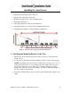
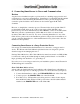
Installing the SmartSensor Installing the SmartSensor involves seven simple steps: 1. Attaching the mounting bracket to the pole; 2. Applying silicon dielectric compound; 3. Attaching the SmartSensor to the mounting bracket; 4. Aligning the SmartSensor; 5. Connecting SmartSensor cable to the SmartSensor; 6. Connecting SmartSensor to Power and Communication Devices; 7. Configuring the SmartSensor using SmartSensor Manager™. Figure 1 – Detection range of a properly mounted SmartSensor 1.
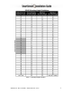
Table 1 – Mounting Height Guidelines SmartSensor 105 User Guide – Wavetronix LLC 9/20/07 - 7-
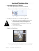
2. Applying Silicon Dielectric Compound 1. Take the tube of Silicon Dielectric Compound and tear off the tab. 2. Squeeze about 25% of the silicon into the connector at the base of the SmartSensor as shown in Figure 2. Be sure to wipe off any excess compound. Figure 2 – Applying Silicon Dielectric Compound 3. Attaching the SmartSensor to the Mounting Bracket 1. Align the bolts on the back of the SmartSensor with the holes in the mounting bracket.
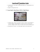
2. Adjust the side-to-side angle to within approximately ±2° of perpendicular to the flow of traffic. 3. Tighten mounting bracket bolts. 5. Connecting the SmartSensor Cable to SmartSensor Figure 4 – Attached Cable 1. Attach the cable connector to the 25-pin connector at the base of the SmartSensor as shown in Figure 4. The SmartSensor connector is keyed to ensure proper connection; simply twist the connector clockwise until you hear it click into place. 2.
6. Connecting SmartSensor to Power and Communication Devices A typical sensor installation requires a pole-mount box containing surge protection and connections for power and communications. SmartSensor is compatible with all standard control cabinets; a table describing the SmartSensor cable’s pin-out and appropriate connection points inside the control cabinet can be found in Appendix B of this document.
Figure 5 – Short Distance Cable Run Long Cable Run (41-100 feet) A long cable installation includes any installation with a SmartSensor cable longer than 40 feet. Follow the steps below to correctly add surge protection to a long cable run (see Figure 6): 1. Connect the SmartSensor cable from the SmartSensor to the PROTECTED side of the Click! 200. 2. Mount a Click! 200 (or equivalent) device on the same pole as the protected sensor, and mount another Click! 200 in the cabinet. 3.
Figure 6 – Long Distance Cable Run SmartSensor 105 User Guide – Wavetronix LLC 9/20/07 -12-
The Click! 200 has 12 screw terminal connections on both the top and the bottom (see Figure 7). The screw terminals on the top of the module are surge protected: Back The back four terminals consist of one +DC power, -DC and two surge ground connections; Middle The middle four terminals are for RS-485 communication and consist of a +485 connection, a -485 connection and two connections for ground.
Wire the SmartSensor cable to the Click! 200 according to Table 2: Table 2 – Click! 200 Connections NOTE: See Appendix F for a description of how to wire the Click! 200 using the old SmartSensor cable as well as for a cable connector pin-out diagram. 7. Configuring SmartSensor with SmartSensor Manager™ After the SmartSensor is installed, it must be configured to the roadway for proper operation. The SmartSensor Manager software is used to perform this configuration. Automatic Configuration 1.
a telephone number); or Ethernet (requires a TCP/IP address). Select the radio button of the appropriate connection method and click OK. If you select Serial Connection and SmartSensor Manager cannot find a SmartSensor connected to the serial port, then a “SmartSensor was not detected…” window will appear on your screen. Check the serial and power connections and click on OK. 4. When a successful connection is made, select Lane Configuration from the Edit menu. 5.
Manual Configuration If the sensor is unable to automatically configure itself to your satisfaction, you can manually configure it by adding, removing or adjusting lanes, lane dividers and lane centers. Figure 8 – Automatic and Manual Modes 1. With the Lane Configuration page open, select the Manual button; the buttons in the toolbar on the right of the screen will change from gray to black (see Figure 8). 2. The newly activated buttons will remain pressed when you click them.
The cursor will change from an arrow to a hand when it is positioned over a “draggable” line. Lane centers (pink lines) only appear when the cursor is placed directly over them. Figure 9 – Adjusting Lanes Also, you will notice that shoulders, dividers, or centers cannot be dragged past each other. Figure 9 shows the pressed Adjust Lanes button, the hand cursor and the adjustable or draggable lines.
Remove Lane The Remove Lane button allows users to remove entire lanes by moving the mouse cursor arrow to the desired lane. When the arrow changes to a hand, click the left mouse button and the selected lane will disappear. Construct and Remove Road To insert a new road, click on the Construct Roads button and select a location anywhere in the background (khaki colored) area. Make sure the cursor appears as a hand and then click the left mouse button to draw the road.
To do this, press the Reverse Direction button and move the cursor over the lane you wish to change. Once the cursor is in place, the cursor will again change from an arrow to a hand and a tiny arrow will appear below the hand to indicate the current direction of that lane. Figure 10 – Reversing Direction Click the left mouse button, and the tiny arrow will reverse direction to verify the change has occurred (see Figure 10).
Figure 11 – Editing Lane Names To do this, click on the Edit Lane Name button and an Edit Lane Names window will appear (see Figure 11). Highlight the current lane name by double clicking on it with the mouse, and then type in the lane’s new alpha-numeric identification of up to eight characters. Lane names can also be changed by going to Sensor Settings and clicking on the Data Collection tab.
Undoing Manual Changes Unsaved changes may be undone without repeating the manual configuration process. Click on the Undo button found below the manual tool buttons (see Figure 12). This tool retrieves the last saved configuration from the SmartSensor, effectively undoing any unsaved changes that were made.
Figure 14 – Lane Configuration Page in Manual Mode Figure 15 – Traffic/Event Data View Mode SmartSensor 105 User Guide – Wavetronix LLC 9/20/07 -22-
A window will appear indicating that the changes are being saved to the SmartSensor. After the changes have been saved, SmartSensor Manager will automatically change from Lane Configuration to Traffic/Event Data View mode. Figures 14 and 15 illustrate the differences between these two modes. Configuration Summary After completing the steps listed above and having read over some of the configuration basics, the SmartSensor should now be installed and configured correctly.
Appendix A – SmartSensor Specifications Operating Frequency: 10.525 GHz (X-band) Detection Zones: Up to 8 traffic lanes simultaneously Detection Range: 60 m (197 ft.) Measured Quantities: Communications: Speed, occupancy, volume, presence RS-232 and RS-485 connection Power: 7.5 watts @ 10-30 VDC Weight: Less than 5 lbs. Or 2.27 kg Physical Dimensions: Zone Resolution: Ambient Operating Temp: Humidity: Shock: Transmitted Power at 3m: 32 cm x 23 cm x 7.
Appendix B – Cable Connector Definitions The SmartSensor cable is comprised of three groups of wires. Each group contains colorcoded wires accompanied by a drain wire and surrounded by a shield. The following table details the pin out of the cable and the appropriate connection inside the cabinet for each wire: Table 3 – SmartSensor Cable and Cabinet Connection See Figure 16 for a diagram of the previously used SmartSensor cable’s 25-pin socket assignment.
Figure 16 - SmartSensor SS105 Plug Connector Socket Assignment as seen from the solder cup side of the connector.
Appendix C – RS-232 Communication Communication between the SmartSensor and PC can be established using the RS-232 DTE specifications, along with the use of a Null Modem cable and the standard 9-pin “D” male connector. Please use the following guidelines for connecting the SmartSensor cable to the serial connection on a PC or modem when not using a Click! 200. NOTE: The RS-232 pin outs remain the same on the SmartSensor cable regardless of connecting to a PC or a modem.
Figure 18 – Connecting a Modem to the SmartSensor Figure 19 – Rear view of RS-232 DB9 serial connector SmartSensor 105 User Guide – Wavetronix LLC 9/20/07 -28-
Appendix D – RS-485 Communication RS-485 communication between the SmartSensor and PC may be established by using the SeaLink +485 model #2102 RS-485 to USB converter by SeaLevel, along with the standard 25-pin “D” female connector with the following pin out: 1: No Connection (N/C) 2: -485 3: -485 4: N/C 5: N/C 6: N/C 7: GND 8: N/C 9: N/C 10: N/C 11: N/C 12: N/C 13: N/C 14: +485 15: N/C 16: +485 17: N/C 18: N/C 19: N/C 20: N/C 21: N/C 22: N/C 23: N/C 24: N/C 25: N/C Appendix E – Labeling The following la
Appendix F – Old Cable Connector Definitions The previously used SmartSensor cable is comprised of six twisted pairs of wire. Each pair is comprised of a black and a red wire, accompanied by a drain wire and surrounded by a shield. A numeric label (1 through 6) identifies each pair of black and red wires.
Figure 20 - Click! 200 Wiring (Old) See Figure 21 for a diagram of the previously used SmartSensor cable’s 25-pin socket assignment. The codes listed in the diagram are to be used to solder wires into the back of the plug where the letters represent the individual solder cups.
Figure 21 – Old SmartSensor SS105 Plug Connector Socket Assignment as seen from the solder cup side of the connector.
Communication between the SmartSensor and PC can be established using the RS-232 DTE specifications, along with the use of a Null Modem cable and the standard 9-pin “D” male connector. Please use the following guidelines for connecting the SmartSensor cable to the serial connection on a PC or modem when not using a Click! 200. NOTE: The RS-232 pin outs remain the same on the SmartSensor cable regardless of connecting to a PC or a modem. If connecting to a PC, a null modem cable is required (see Figure 22).
Table 7 – Belden 9331 (Old Cable) Conversions SmartSensor 105 User Guide – Wavetronix LLC 9/20/07 -34-
Appendix G – Cable Lengths The following recommendations allow the user to provide reliable power to the SmartSensor. The SmartSensor cable’s red and black wires provide a 20 AWG wire pair. The other pairs on the SmartSensor cable are 22 AWG and are normally used for communication.
mounted next to the sensor. In this case, the homerun connection establishes one RS-485 channel over the normal white/blue wire pair and another RS-485 channel over the yellow/violet wire pair. An additional Click! 304 is needed to convert the data sent over the yellow/violet wire pair back to RS-232 before connecting to surge protection. If you elect to use an alternate cable for power, you may also want to select an alternate cable for RS-485 communications.