Wavetec Pvt. Ltd. Spectra Controller Installation Guide Haider Ali 9/4/2020 Rev 1.
Document History Revision Date Comments Prepared By 1.
Contents Document History ......................................................................................................................................... 2 Contents ........................................................................................................................................................ 3 1. Introduction .......................................................................................................................................... 4 2.
1. Introduction This guide defines the installation procedure of Spectra Controller. Spectra controller is the main component in EQ system and can be used to drive displays which is described in this document. The back side of the controller has all the ports and the front side has the company’s logo that glow when unit is powered ON. 2. Items Included in Package Item Specs Quantity 1 Spectra Unit Refer to Specs Sheet 1 2 Power Supply Meanwell 12V/3.
3.
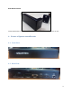
Rack Mount Brackets These two brackets can be screwed on sides of spectra unit in order to mount it on rack. 4. Picture of Spectra controller unit 4.1 Front View: 4.
5. Ports Description Back panel of Spectra: Volume KnobRotate clockwise to increase volume To Active HUB “IN” Port (Only used in serial mode) RS485 (Cat5e/CAt6) Cat5e/Cat6 LAN cable 2 x 8Ω speaker Power adapter 12V 3.
The controller provides following functionalities: Power 2.5mm DC Jack to Power up the unit with Meanwell supply (12V, 3.34A) included in package. CDU ports RJ45 Ports marked CDU can be used to drive Display devices over RS485 protocol (Active Hub will be needed). Audio Two RJ45 ports for connecting 8 Ohm speakers. Volume Knob for controlling volume level. Debug port (DB-9 Connector) A standard FTDI cable (RS232 to USB) can be plugged into this port for debugging purpose.
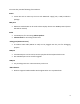
6. Setting up Spectra 6.1 Setting up Spectra in wired system 6.1.2 TCP/IP Mode (Recommended) Wiring Diagram: Output- RS485 (Cat5e/CAt6) Power adapter 12V 3.
Description: Connect the Spectra controller as shown in wiring diagram above. When using TCP Active Hub, Spectra can be configured to transfer data for displays (CDUs, SDUs and PDUs) and HTSUs over TCP/IP connection to TCP Active Hub. TCP Active Hub must be connected to same local network as Spectra is connected to.
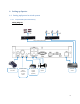
6.1.3 Serial Mode (over RS485) Wiring Diagram: Volume Knob - Rotate clockwise to increase volume Power adapter 12V 3.43A To connect external amplifier or headphone (optional) 2 x 8Ω speaker Ethernet switch Description: Connect the Spectra controller as shown in wiring diagram above.
Refer below image for reference (TCP Active Hub): Patch cord (Cat5e or Cat6) Note: It is recommended to use Cat5e or Cat6 LAN cable/Patch cord Length of wire between Spectra controller “CDU” port and “IN” port of Active Hub can go up to 50m. 6.2 Providing LAN connectivity: Connect a LAN cable/Patch cord from network switch to LAN port on Spectra controller in order to provide internet or LAN connectivity. 6.
7. Debugging: 8.
9. External Amplifier - Connections Audio Aux Cable 3.
10.
This device complies with part 15 of the FCC Rules. Operation is subject to the following two conditions: (1) This device may not cause harmful interference, and (2) this device must accept any interference received, including interference that may cause undesired operation. FCC warning: Any Changes or modifications not expressly approved by the party responsible for compliance could void the user's authority to operate the equipment.