
User Guide

Hardware Specification
2018 Microchip Technology Inc. DS50002751C-page 63
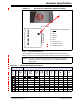
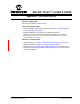
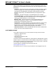
FIGURE B-2: MPLAB PICkit 4 DEBUGGER CONNECTOR PINOUT
B.3.2 Pinouts for Interfaces
The programming connector pin functions are different for various devices and
interfaces. Refer to the following pinout tables for debug and data stream interfaces.
Pin 1 Indicator
1
2
3
4
5
6
7
8
MPLAB PICkit 4
MPLAB PICkit 4 Pin Description*
1 = MCLR
2 = VDD
3 = Ground
4 = PGD
5 = PGC
6 = Do not connect
7 = Unused for ICSP
8 = Unused for ICSP
Note: Refer to the data sheet for the device you are using as well as the
application notes for the specific interface for additional information
and diagrams.
TABLE B-5: PINOUTS FOR DEBUG INTERFACES
MPLAB PICkit 4 DEBUG
Connector
Pin #
Pin
Name
ICSP
(MCHP)
MIPS
EJTAG
CORTEX
SWD
AVR
JTAG
AVR
ISP(&Dw)
UPDI
UPDI
AW
DW(IRE)
TPI
1 TVPP MCLR MCLR MCLR
2 TVDD VDD VIO_REF VTG VTG VTG VTG VTG VTG VTG VTG
3 GND GND GND GND GND GND GND GND GND GND GND
4 PGD DAT TDO SWO TDO MISO DAT DAT DATA DAT
5 PGC CLK TCK SWCLK TCK SCK CLK
6TAUX AUX RESET
RESET CLK dW RST
7TTDI TDI TDI MOSI
8TTMS TMS SWDIO TMS