
User Guide

Hardware Specification
2018 Microchip Technology Inc. DS50002751C-page 61
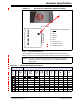
6. Pin 1 Marker - This designates the pin 1 location for proper connector alignment.
7. Programming Connector - The connector is an 8-pin SIL header (0.100" spacing)
that connects to the target device. See Table B-6 for the pinout specifications.
8. Micro SD Card Slot
1
- The micro SD card slot supports a large variety of microSD
cards with various speed requirements.
B.2.1 Main Board
The main board includes the following features:
• A 32-bit microcontroller using an ARM® Cortex®-M4 core
• A USB 2.0 interface capable of USB speeds of 480 Mbps
• An SRAM for holding the program code image. This image is used for
programming on-board Flash device.
• One LED
B.2.2 Indicator Light Strip
The expected start-up sequence for the MPLAB PICkit 4 debugger is:
1. Purple - steady on for approximately 4 seconds
2. Blue - steady on. The debugger is ready.
The indicator light strip has the following significance.
The following tables provide descriptions of the indicator lights and bootloader errors.
1.This functionality is coming soon with a firmware update of the product through MPLAB X IDE.
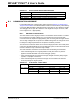
TABLE B-1: TYPICAL LIGHT STRIP DESCRIPTIONS
Color Description
Blue Power is connected; debugger in standby.
Orange Power target circuit from PICkit 4 checked
Green Power target circuit from PICkit 4 unchecked
Red Lit when the debugger has failed.
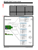
TABLE B-2: ADDITIONAL LIGHT STRIP DESCRIPTIONS
Light Strip Description
Normal Modes
Blue Power is connected; debugger in standby
Orange Power target circuit from PICkit 4 checked (Table A-4)
Green Power target circuit from PICkit 4 unchecked (Table A-4)
Purple Bootloader is running
Yellow Debugger is busy
Red An operation has failed
Purple Fast blink indicates the time window for forcing the debugger
into Bootloader mode