
User Guide


MPLAB
®
PICkit™ 4 User’s Guide
DS50002751C-page 60 2018 Microchip Technology Inc.
B.2 MPLAB PICKIT™ 4 IN-CIRCUIT DEBUGGER
The debugger consists of an internal main board and an external Micro-B USB
connector and an 8-pin SIL connector. On the face of the debugger enclosure is an
indicator light strip and a push button located under the logo.
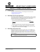
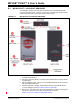
FIGURE B-1: MPLAB PICkit 4 IN-CIRCUIT DEBUGGER
1. Lanyard Connection - An opening through the top and side for a lanyard (not
included) to be attached.
2. Emergency Recovery Button - If needed, this recessed button is used for Recov-
ery Boot Mode.
3. Micro-B USB Connector - Used to connect the MPLAB PICkit 4 to the computer
with the supplied USB cable.
4. Indicator Light Strip - Displays the operational modes of the MPLAB PICkit 4
in-circuit debugger (see Section B.2.2 “Indicator Light Strip”).
5. Button Area - The area in the center of the shield logo is used for the Program-
mer-To-Go
1
option and for invoking the bootloader mode (see
Section 4.4.2 “How to Invoke the Bootloader Mode”).